10
Using the Control Module
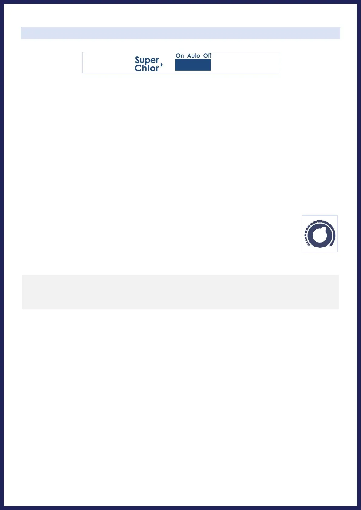
SWITCH POSITIONS:
• AUTO: Normally, this switch should be left in the “Auto” position. In this position the Universal Series will
produce sanitizer according to the percentage chosen by the "Output Adjustment Dial".
• ON: This position turns on the “Super Chlor” feature, for when a larger amount of sanitizer is temporarily
needed to contend with high bather loads, heavy rainfall, or cloudy water conditions. This boosts output from its
current dial position to 100% output for 24 hours (filter pump must be on during this time) or until the power
has been turned off, whichever comes first. At the end of the Super Chlor period, the system will revert to
operation based on the Output Adjustment Dial - put the switch back into the “Auto” position when next able.
• OFF: The “Off” position prevents the Control Module from energizing the Electrolytic Cell. In this position there
is no chlorine generation. IMPORTANT SAFETY NOTE: The OFF position does not remove power from the
Control Module. Always disconnect power at the circuit breaker prior to attempting any service procedure.
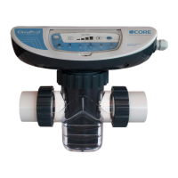
OUTPUT ADJUSTMENT DIAL:
The yellow dial is used to control the amount of chlorine the Cell generates. The chlorine output is
adjustable from 5% to its 100%.
LED INDICATOR LIGHTS:
• Power: The Control Module is receiving input power when this light is illuminated.
• Generate: This LED is illuminated during normal operation (when switch is in On or Auto position). When
flashing, the pool water is either too hot or too cold for chlorine generation. This LED is only off when the
Super Chlor switch is in the Off position.
• Super Chlor: This LED is illuminated when the Super Chlor mode is active and the switch is in the On position.
• Remote: The Control Module is controlled by a remote control system. (Check with dealer for availability)
• No Flow: This LED is illuminated solidly when the Flow Switch has detected no flow. This causes the Cell to
stop generating chlorine. A flashing LED indicates that the flow is restored, but there will be a 60 second
delay before generation is reestablished.
• Cell Maint.: A flashing LED is only a reminder that enough time has gone by that you should proactively inspect
the inside of the cell. The flashing light does not impact operation, and is reset by holding the “system status”
button for 10 seconds. A solidly illuminated LED indicates Cell efficiency is greatly reduced and the Cell has
stopped producing chlorine. This will eventually happen with normal operation, and at this point the cell simply
must be cleaned: see instructions on page 12. Be sure to inspect the cell after cleaning; look through the cell to
make sure there are no physical particles or blockages between the titanium plates. If after cleaning the Cell
Maint. light comes back on within 10-15 minutes of operation, verify salinity and Cell Version setting, and then
continue to clean cell again more thoroughly as needed. It is possible for cleaning to be necessary even if debris or
mineral build-up isn't immediately visible to the eye. Additionally, if inadequate water flow through the cell is not