16
Installing the Control Module
Mount the Control Module as close to the pump and filtration system as possible. For safety concerns, do not install
the Control Module within 10 feet of the pool edges, and follow all applicable codes. Verify that the Cell and Flow
Switch cables can reach the Control Module from the section of pipe selected for plumbing.
The Module is fully rated for outdoor use; common sense considerations such as minimizing direct exposure to rain,
sunlight, water runoff, and lawn sprinkler systems will enhance longevity. As with most electronics, avoid placing the
controls above a heater or in tightly enclosed or insulated spaces to avoid a build-up of excess heat.
Using screws, secure the Control Module's mounting bracket at a comfortable level on a wall or vertical support, at
least 3 feet above ground level. Hang Controls on bracket.
Wiring
CAUTION: Power must be shut off at the circuit breaker before performing any wiring. Be sure to follow local and
NEC/CEC electrical codes. The system has been designed to easily wire into typical in-ground pool systems. To
provide safe operation, the unit must be properly grounded and bonded.
For operation, the Control Module may be wired in to the pump's power source so that both turn on and off
together, or energized continuously for use with variable speed pumps (Flow switch will control Cell power but lights
will remain on).
Bonding:
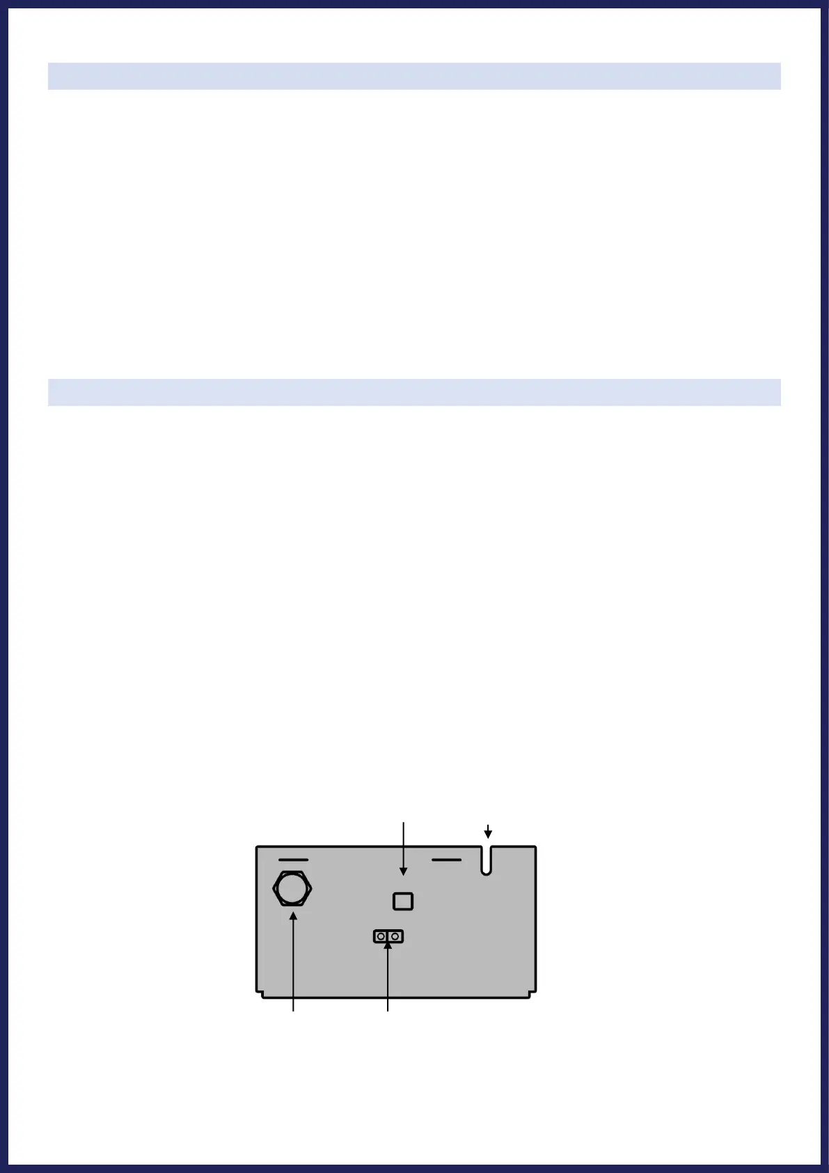
A lug used for attaching a bonding ground is located on the bottom of the UNIVERSAL-Series Control Module. The
Control Module must be bonded with an 8 AWG bare copper wire to the pool bonding system.
Electrolytic Cell and Flow Switch Connections:
The Cell and Flow Switch cables have easy plug-in connectors, which attach easily to the Control Module. Refer to
the diagram below for the location of these connections. Carefully align each connector to avoid damage.