PENDIENTE DE VALIDACIÓN
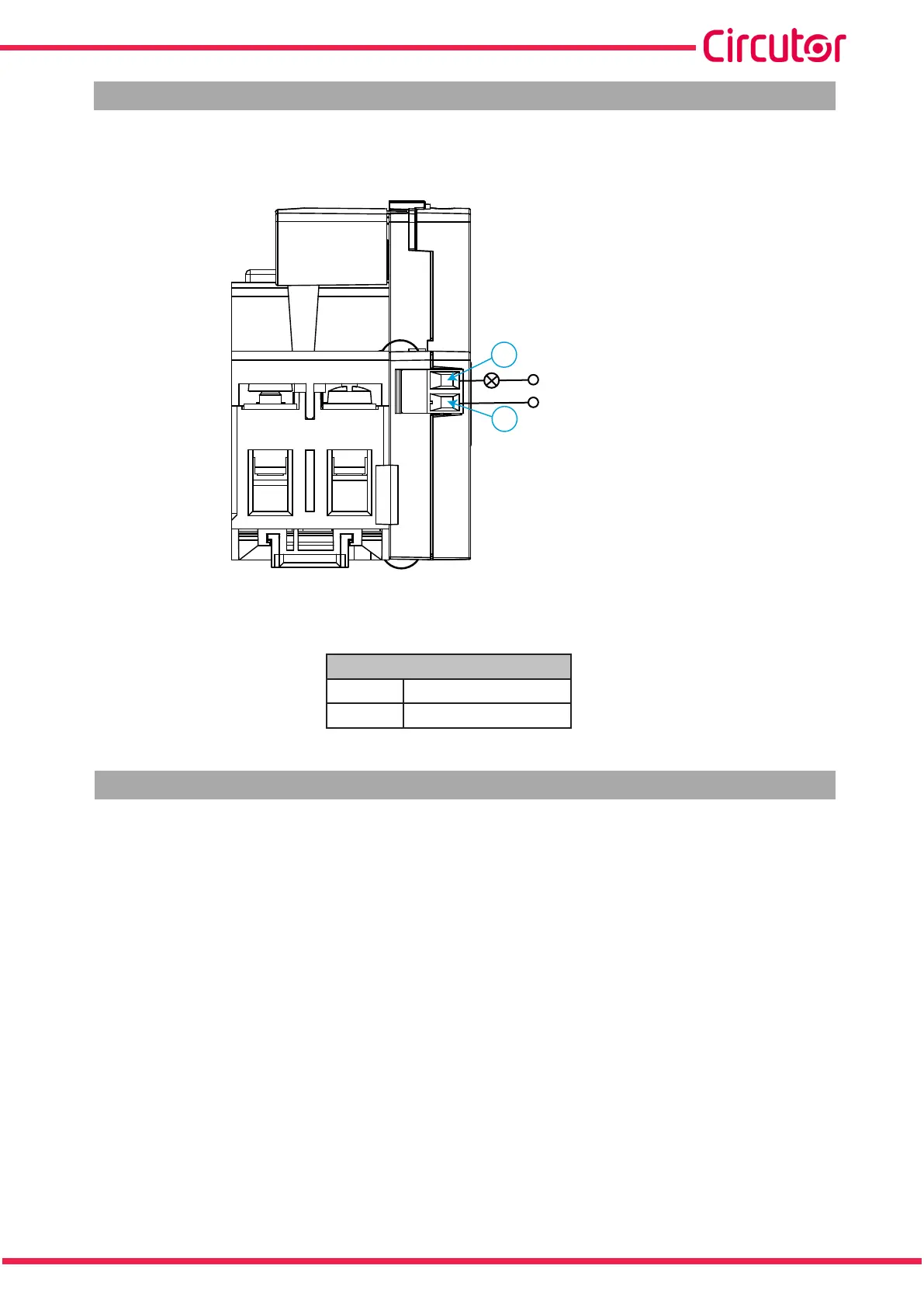
4.3.-INDICATION OUTPUT (Model REC4-C)
The REC4-C model has an output that indicates the blocking of the device when the maximum number
of reconnections is exceeded (Figure 6 and Table 6).
7
8
Vmax: 300 Vac/dc
Imax: 0.1 A
Figure 6: Indication output (REC4-C).
Table 6: REC4-C terminals.
Terminals
7 Indication output
8 Indication output
4.4.- START-UP
Once the device is installed you must carry out the following start-up sequence for it to work properly.
4.4.1.- AUTOMATIC MODE
If the device is going to operate in automatic mode, see Section “4.5.2.- AUTOMATIC”, the start-up se-
quence is:
1.- Put the mode selector switch in Manual Mode (OFF).
2.- Lift the RCCB cover.
3.- Put the RCCB contact in ON mode.
4.- Lower the RCCB cover.
5.- Put the mode selector switch in Automatic Mode (ON).
Note: The switch has an M2 hole where you can attach a seal or a padlock to block access to the RCCB
and any other attempts at manual reclosing (Figure 7).
13
Instruction Manual
REC4