PENDIENTE DE VALIDACIÓN
3.3.- CONNECTION
The REC4 must be connected to an installation protected with fuses suitable for its power supply range
and consumption.
Note: Cross-section of the cable: 16 - 25mm
2
Terminals, opening covers or removing elements can expose parts that are hazardous
to the touch while the device is powered
If the REC4 indicates a permanent failure (AUTO and REC LEDs are lit), you must
check the RCCB and the installation.
If the installation of the device is done with the RCCB in the OFF state, when panel
receives voltage the device will not activate the automatic reclosing system for safety
reasons And the AUTO and REC LEDs turn on to turn off in a few seconds. A manual
reclosing of the system must be done on the panel with voltage.
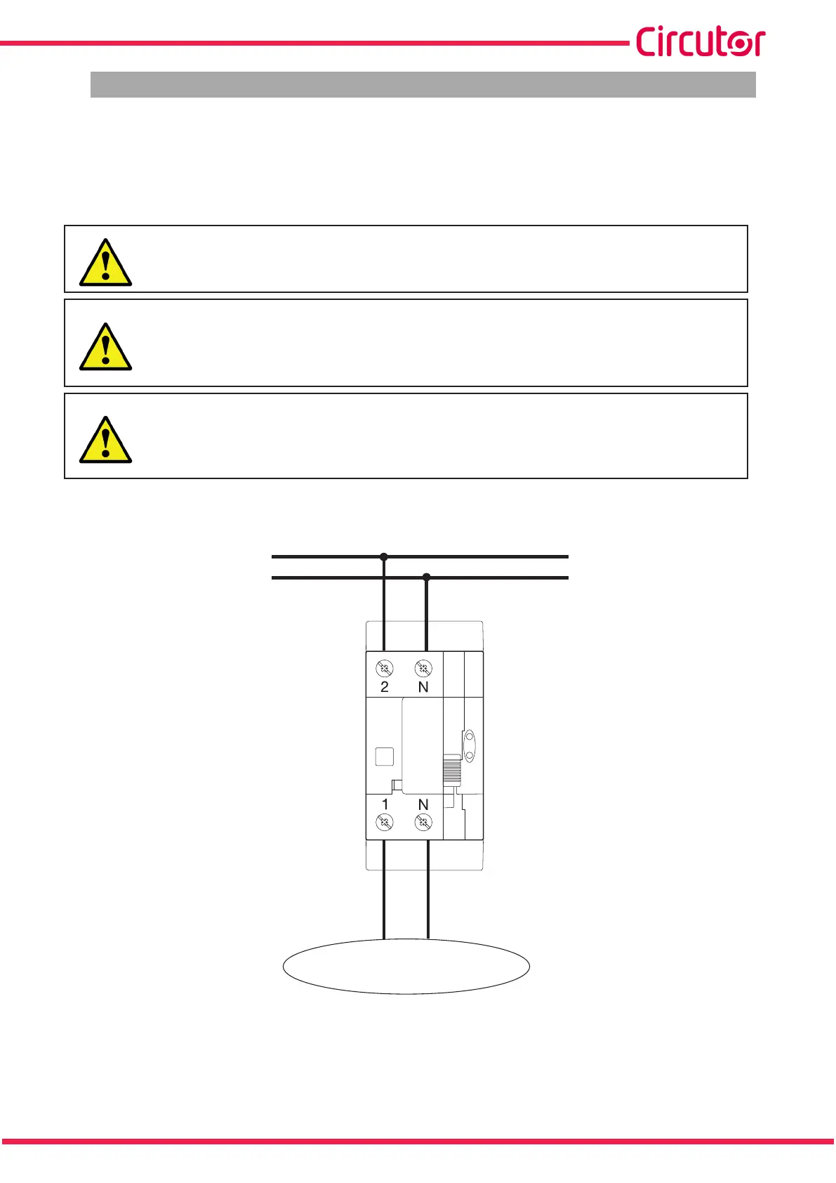
3.3.1.- CONNECTION DIAGRAM 2-POLE MODEL: REC4-2P, REC4-C-2P
F
N
CARGA / LOAD
Figure 1: Connection diagram REC4-2P, REC4-C-2P.
9
Instruction Manual
REC4