Page 28
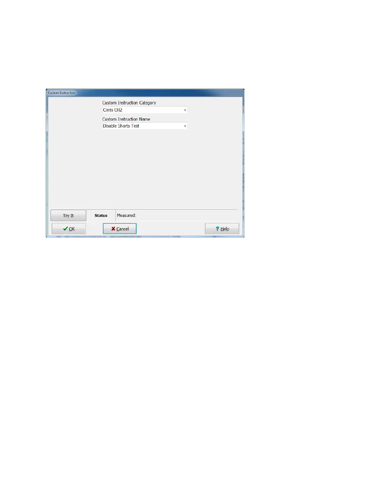
Disable Shorts Test
When testing a DUT, the CH2 tester first uses low voltage to verify the existence of the connections listed
in the test program, and then automatically performs a low voltage isolation test called the shorts test.
This custom instruction can be placed anywhere in the test instruction list to turn off the automatic shorts
test. Typically this is only done when the test programmer chooses to use the LV and HV isolation tests
to ensure isolation between critical test points.
Two Point LV Isolation Test
Two Point LV Isolation allows you to perform a low voltage isolation test between two points, each of
which may be part of larger nets. When this custom instruction is executed, the tester applies the
specified source current to one point (the Hi Point) at a voltage that will not exceed the compliance
voltage, which may be set between .25 and 10 volts. The tester sinks the other isolation point (the Low
Point), and floats all other test points. This custom instruction allows you to set the isolation resistance
(Minimum IR Resistance). If the measured resistance is greater than Minimum IR Resistance, the custom
instruction will pass. If measured resistance is less than Minimum IR Resistance, the test will fail.
Note that the tester can perform LV isolation tests faster than it can HV isolation tests. Another
advantage is that the test voltage can be set low enough to ensure that any DUT circuitry is not damaged.
Note that setting a higher compliance voltage will allow the tester to sense higher isolation resistances
and with greater resolution.
Use Two Point HV Isolation Test if you need to perform an isolation test at voltages over 10 volts.
Two Point HV Isolation Test
The Two Point HV Isolation allows you to perform a high voltage isolation test between two test points,
each of which may be part of larger nets. The high voltage test consists of two parts – a Dielectric
Withstand Test (DW Test) and an Insulation Resistance Test (IR test). The DW test is performed first. In
this test the tester applies the selected DW Voltage (from 10 volts to the highest capability of the tester)
and monitors current flow. The specified sink point is sunk to ground. All other test points are floated.
Any spike in current flow above the DW Total or Real Current settings causes the DW test to fail. During
the IR test, the tester attempts to raise the source point to the selected IR Voltage, which must be equal
to or less than the DW Voltage setting. Again the tester sinks the specified sink point to ground and floats
all other test points. Current flow into the source test point is measured as it relates to isolation
resistance (IR). If the measured resistance is lower than the minimum IR resistance setting, the test fails.