29
Configuring an ADSL WAN Interface Card on Cisco 1700 Series Routers
OL-3317-03
Configuring FRF.5 and FRF.8 Internetworking Functions
Parallel reads to TCQ:0 tx count reset = 0, periodic safe start = 0
Serial idb(AAL5) output_qcount:0 max:40
Serial idb(RAW) output_qcount:0, max:40
Sar ctrl queue: max depth = 10, current queue depth = 0, drops = 0, urun cnt = 0, total
cnt = 99
Serial idb tx count: AAL5: 0, RAW: 0, Drop count:AAL5: 0, RAW: 0
SCC Clockrates:
SCC-A = 5300000
SCC-B = 4000000
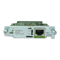
WIC Register Value Notes
---- ----------- ---------- ----------
FPGA Dev ID (LB) 0x44 'D'
FPGA Dev ID (UB) 0x53 'S'
FPGA Revision 0xA1
WIC Config Reg 0x4D WIC / VIC select = WIC;
Configuring FRF.5 and FRF.8 Internetworking Functions
To communicate over WANs, end-user stations and the network cloud typically must use the same type
of transmission protocol. This limitation has prevented differing networks such as Frame Relay and ATM
from being linked. The Frame Relay–to–ATM Service Interworking feature allows Frame Relay and
ATM networks to exchange data despite differing network protocols. The functional requirements for
linking Frame Relay and ATM networks are provided by the Frame Relay/ATM PVC Service
Interworking Implementation Agreement specified in Frame Relay Forum (FRF) documents FRF.5 and
FRF.8. The FRF.5 and FRF.8 interworking functions involve multiplexing PVCs between Frame Relay
and ATM networks and mapping the control bits between Frame Relay frame headers and ATM cell
headers. FRF.5 and FRF.8 are necessary for ATM-based features to interwork with Frame Relay–based
IP class of service (CoS) features.
Configuration Examples
These examples show how to configure a mapping between a Frame Relay data-link connection
identifier (DLCI) and an ATM PVC, using the connect command. For a full description of the connect
command as used in the FRF.5 and FRF.8 internetworking functions, refer to Enhanced Voice and QoS
for ADSL and G.SHDSL on Cisco 1700 Series, Cisco 2600 Series, and Cisco 3600 Series Routers.
Note For FRF.5 and FRF.8, you may need to match the maximum transmission unit (MTU) between the ATM
and Frame Relay networks for large size packets.
FRF.5
The following example shows how to create an FRF.5 connection, using the network-interworking
keyword in the connect command.
interface serial0
no ip address
encapsulation frame-relay IETF
no fair-queue
frame-relay interface-dlci 100 switched
frame-relay intf-type dce
!
interface atm1
 Loading...