4-6
Cisco 1900 Series Hardware Installation
OL-19084-02
Chapter 4 Installing and Connecting the Router
Wall-Mounting the Chassis
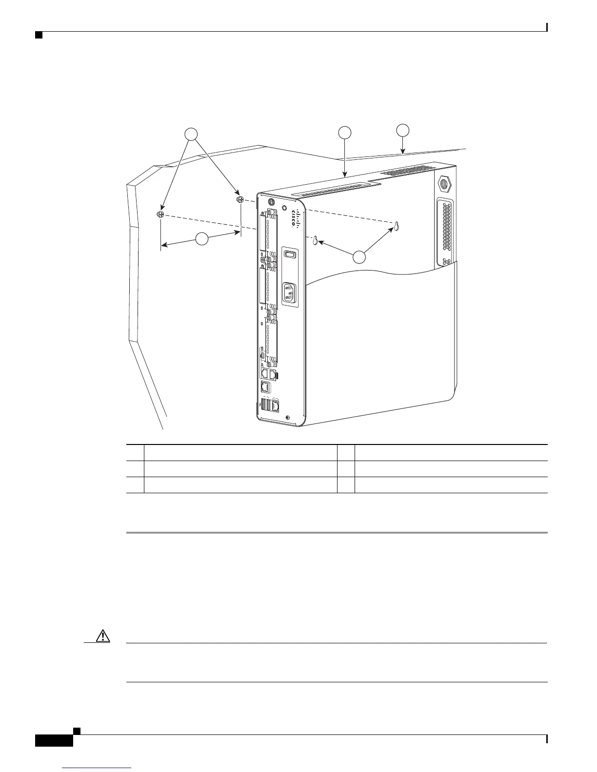
Figure 4-4 shows the wall-mounting features on the Cisco 1941 series routers.
Figure 4-4 Wall-Mounting Features on the Cisco 1941 Router
To mount the router on a wall or other surface, follow these steps:
Step 1 Install the two screws 5.00 inches (12.7 centimeters) horizontally apart on a wall or other vertical
surface.
The screws should protrude 0.25 inch (0.6 centimeter) from the surface of the wall.
Step 2 Remove the rubber feet from the router.
Step 3 Hang the router on the screws. This is the appropriate orientation for safe use. (See Figure 4-3 and
Figure 4-4.)
Caution If you install the screws in drywall, use hollow-wall anchors (1/8 inch by 5/16 inch) to secure the
screws. If the screws are not properly anchored, the strain of the cables connected to the router back
panel could pull the router from the wall.
1 Wall screws 2 5 inches (12.7 cm)
3 Chassis mounting holes (on bottom) 4 Router chassis
5 Mounting surface
251360
S
L
L
CONSOLE
AUX
S
L
USB
1
GE 0/1
G
E
0
/
0
0
EN
EN
DO NOT REMOVE DURING
NETWORKING OPERATION
CF 2
CF 1
DO NOT REMOVE DURING
NETWORKING OPERATION
ISM/WLAN
1
5
4
3
2
 Loading...