16
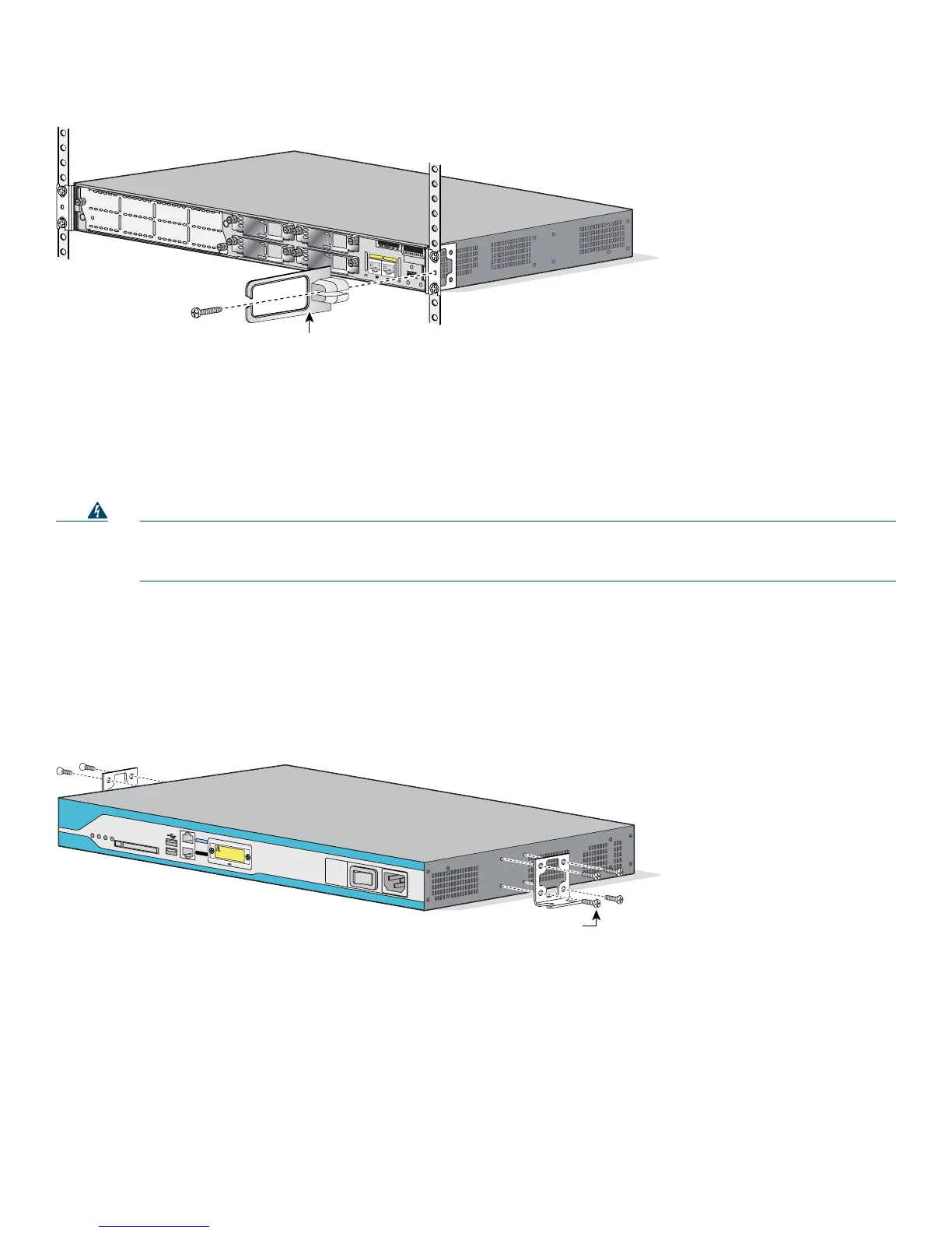
Figure 11 Attaching the Cable Management Bracket to the Cisco 2811 Router
Wall-Mounting the Router—Cisco 2811 Routers Only
You can mount a Cisco 2811 router on a wall. Cisco 2801, Cisco 2821, and Cisco 2851 routers are not designed for
wall-mounting.
Warning
This unit is intended to be mounted on a wall. Please read the wall mounting instructions carefully before
beginning installation. Failure to use the correct hardware or to follow the correct procedures could result in a
hazardous situation to people and damage to the system.
Statement 248
To attach a Cisco 2811 router to a wall or other vertical surface, use the 23-inch (58.42-cm) rack-mount brackets to attach the
router to the wall as described in the following sections.
Attaching Brackets to the Router for Wall Mounting
Attach the standard brackets to the chassis as shown in Figure 12, using the four screws provided for each bracket.
Figure 12 Attaching the Brackets for Wall-Mounting a Cisco 2811 Router
Attaching the Router to a Wall
Attach the router to the wall using the brackets previously attached and attachment hardware that you provide as follows:
• For attaching to a wall stud, each bracket requires two #10 wood screws (round- or pan-head) with #10 washers, or two
#10 washer-head screws. The screws must be long enough to penetrate at least 3/4 inch (20 mm) into supporting wood or
into a metal wall stud.
• For hollow-wall mounting, each bracket requires two wall anchors with washers. Wall anchors and washers must be size
No. 10.
95947
A
=
A
C
T
F
E
0
/1
P
V
D
M
1
P
V
D
M
0
A
IM
1
A
IM
0
F
E
0
/0
S
=
S
P
E
E
D
A
=
F
D
X
A
=
L
IN
K
A
F
S
L
A
F
S
L
S
L
O
T
2
S
L
O
T
0
S
L
O
T
3
S
L
O
T
1
E
N
M
0
Cable management bracket.
Either edge may go up. Attach
to either side of the chassis.
103708
D
o
N
o
t R
e
m
o
v
e
D
u
rin
g
N
e
tw
o
rk
O
p
e
ra
tio
n
C
O
M
P
A
C
T
F
L
A
S
H
C
O
N
S
O
L
E
O
P
T
IO
N
A
L
R
P
S
IN
P
U
T
1
2
V
1
1
A
A
U
X
S
Y
S
P
W
R
A
U
X
/
P
W
R
S
Y
S
A
C
T
C
F
-4
8
V
4
A
1
0
0
-2
4
0
V
~
4
A
5
0
/6
0
H
z
0
1
Screws from
accessory kit
WARNING -- RPS cover
must be installed when
equipment is wall-mounted
and an RPS is not connected
 Loading...