3-22
Cisco 2900 and 3900 Series Hardware Installation
OL-18712-01
Chapter 3 Installing and Connecting the Router
Connecting Power
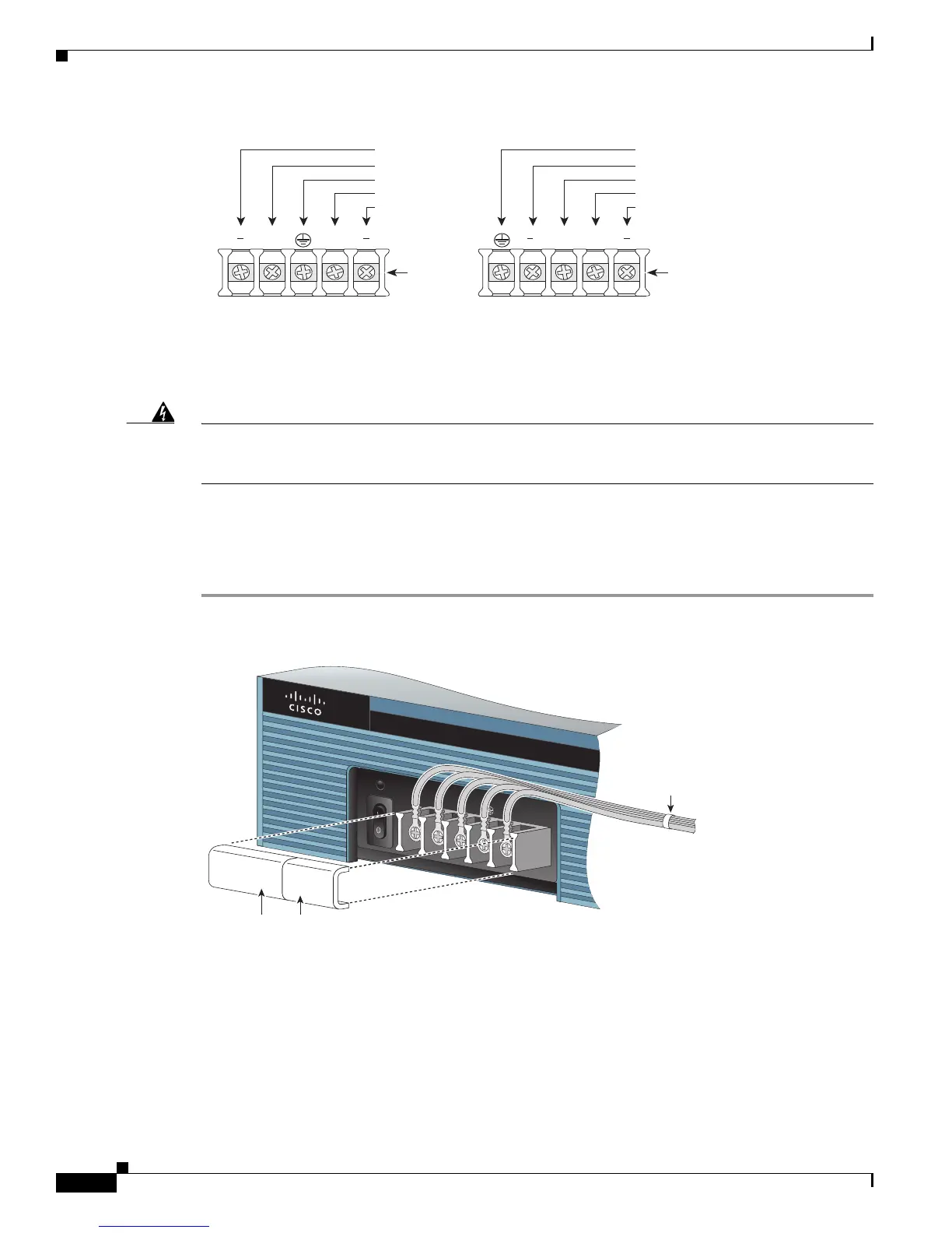
Figure 3-20 DC Power Connections for Cisco 2911, 2921, and 2951 Routers
Step 6
Install the plastic covers over the terminals. (See Figure 3-21 or Figure 3-22.)
Warning
The safety cover is an integral part of the product. Do not operate the unit without the safety cover
installed. Operating the unit without the cover in place will invalidate the safety approvals and pose
a risk of fire and electrical hazards.
Statement 117
Step 7 Organize and secure the wires using cable ties as shown in Figure 2 or Figure 3. Make sure that the wires
do not project above or below the front panel of the router.
Step 8 Turn on power to the DC circuit. Be sure to remove tape used to secure the circuit-breaker switch in the
OFF position.
Figure 3-21 Wire Routing and Attachment for Cisco 2911 Routers
A ++B
2921/2951
Terminal
block
A ++B
2911
Terminal
block
279991
-DC, input A
Return, input A
Safety ground
Return, input B
- DC, input B
Safety Ground
-DC, input A
Return, input A
Return, input B
-DC, input B
From DC
power
source
Cable tie
Plastic covers
 Loading...