5-53
Cisco 2900 Series and 3900 Series Hardware Installation Guide
OL-18712-03
Chapter 5 Installing and Upgrading Internal Modules and FRUs
2911 Front to Back Air Flow Converter
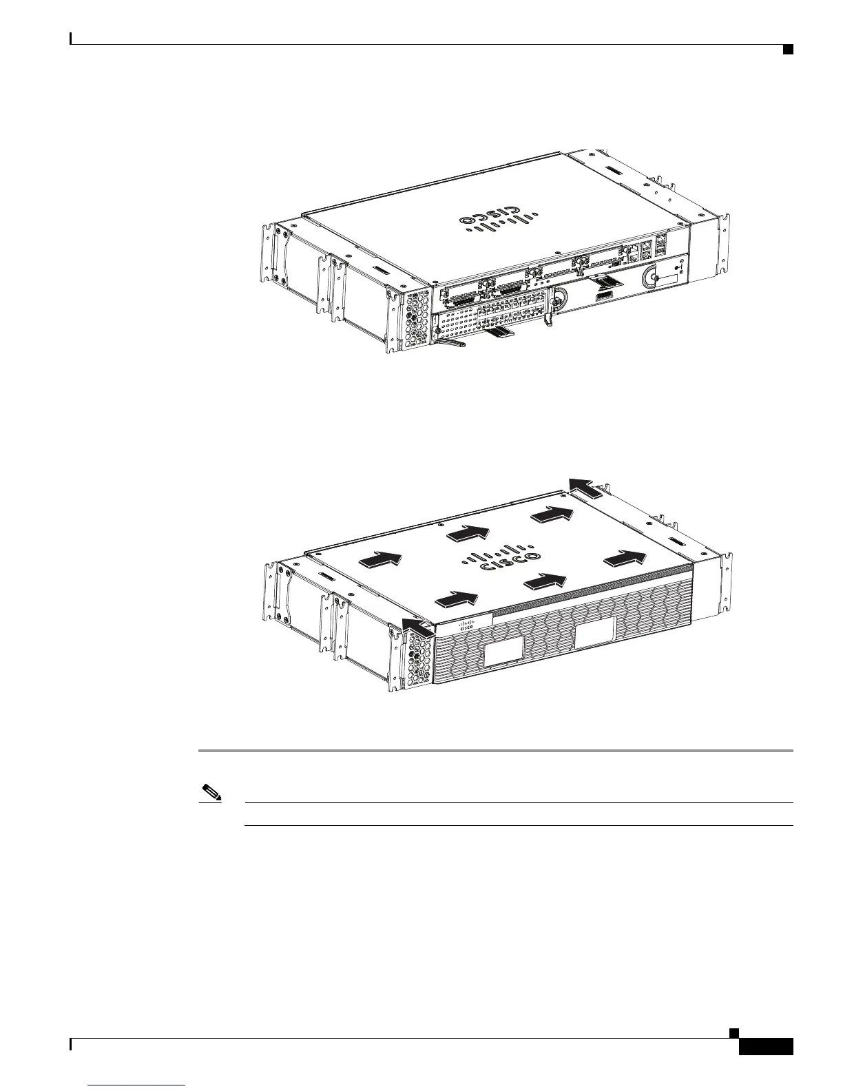
Figure 5-43 Back View of the Cisco 2911 Router with the 2911 Air Converter
Figure 5-44 Front View of the Cisco 2911 Router Showing Forced Front-to-Back Air Flow Scheme
Follow these steps to install the 2911 Air Converter:
Step 1 Remove the screws (three on top and three at the bottom) of the 2911 Air Converter. See Figure 5-45.
Note Set aside these six screws for joining the inner and outer piece in Step 4.
 Loading...