Network Link LED Indicator
The network LED is located on the front panel and indicates if any of the on-board networking ports are connected and operating.
Table 8: Network Link LED Indicator
FunctionLED Indicator Color
Network Link StatusSingle Color
Green
DecodeState
UndefinedOff
Link on any of the ports, but no activityGreen On
Activity on any of the portsGreen Blinking
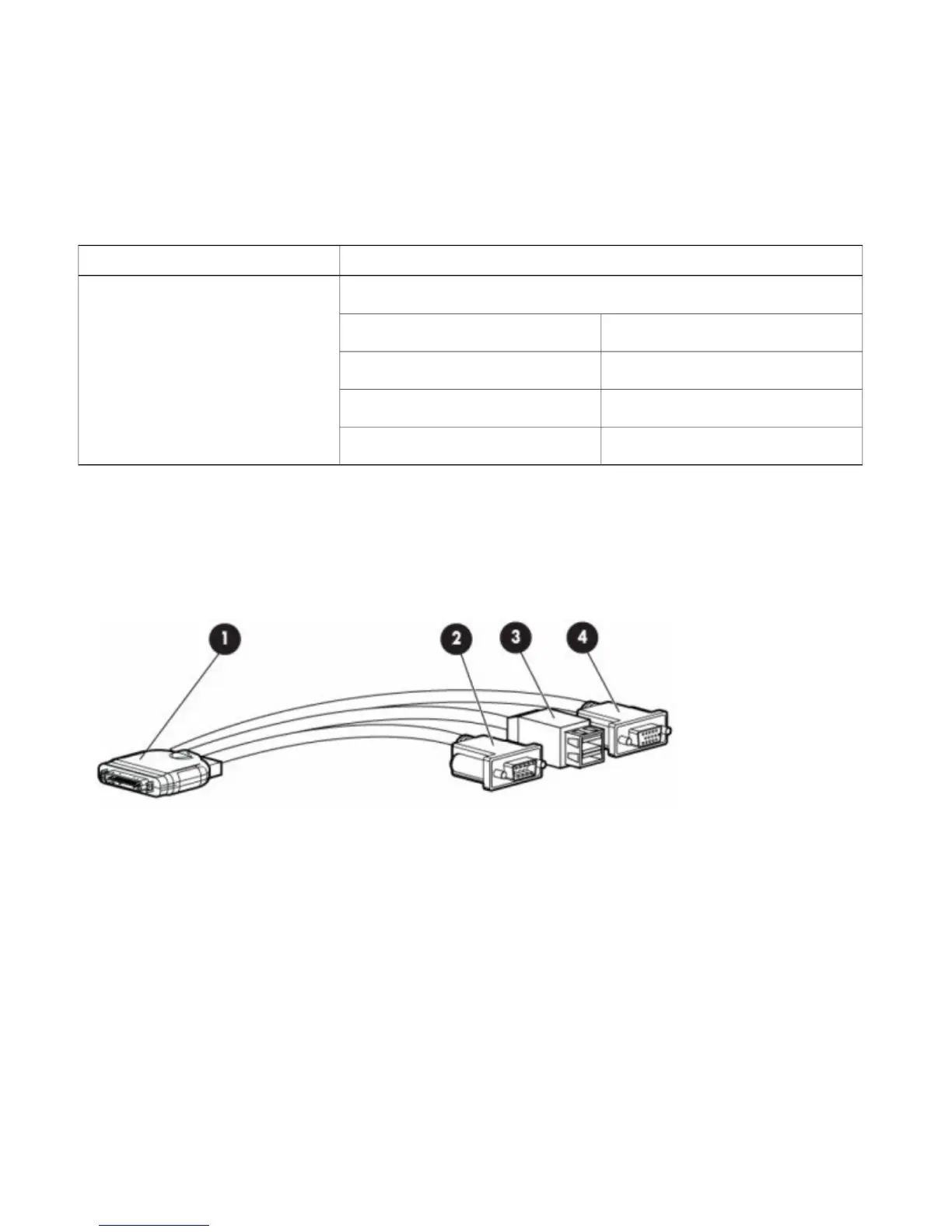
Front Panel KVM Break-out Connector
A single female connector provides access to video, two USB ports for keyboard and mouse, and an RS-232C console serial port.
An external breakout connector to industry standard interfaces is required. The following figure shows an example cable.
The interfaces for the cable are:
1
Front panel KVM/Console connector
2
DB9 serial port connector
3
Dual Type-A USB 2.0 connectors
4
DB15 Video connector
11