Platform Components
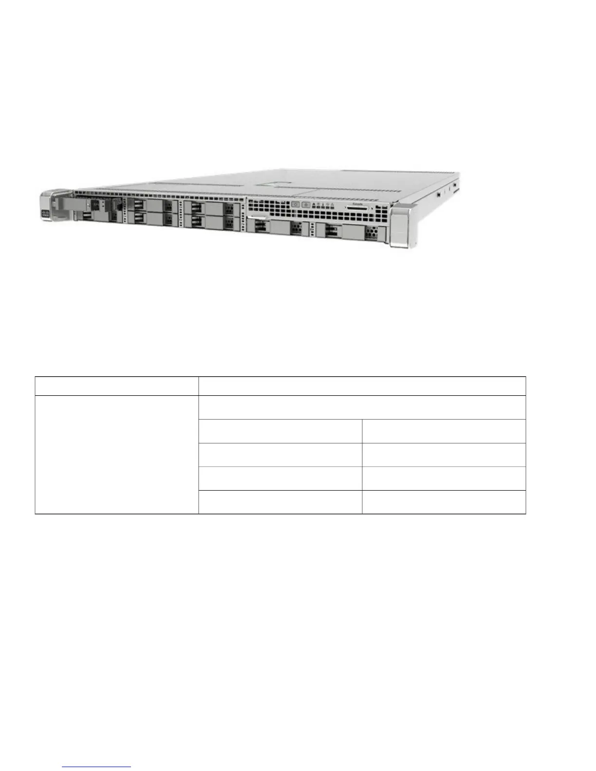
Cisco 5520 WLC Front Panel View
Cisco 5520 wireless LAN controller supports several buttons, LED indicators, and a KVM connector on the front panel. It also
includes a power button and Locator LED button, along with the following LEDS: System status, PSU status, Fan status, Network
LED, and Temperature LED.
Power On Switch and LED Indicator
A Power Button push switch with integrated LED is located on the front panel.
Table 3: Power On Switch and LED Indicator
FunctionLED Indicator Color
Card Power StatusBi-color Yellow
(Amber)
Green
DecodeState
Card Power OffOff
Soft OffAmber On
Card Power OnGreen On
Locator Switch and LED Indicator
A Unit Identify push switch with integrated LED is available on the front panel and rear panel . Each press on the button toggles
between active and non-active states.
System Status LED Indicator
The system status LED located on the front panel indicates the overall system health.
8