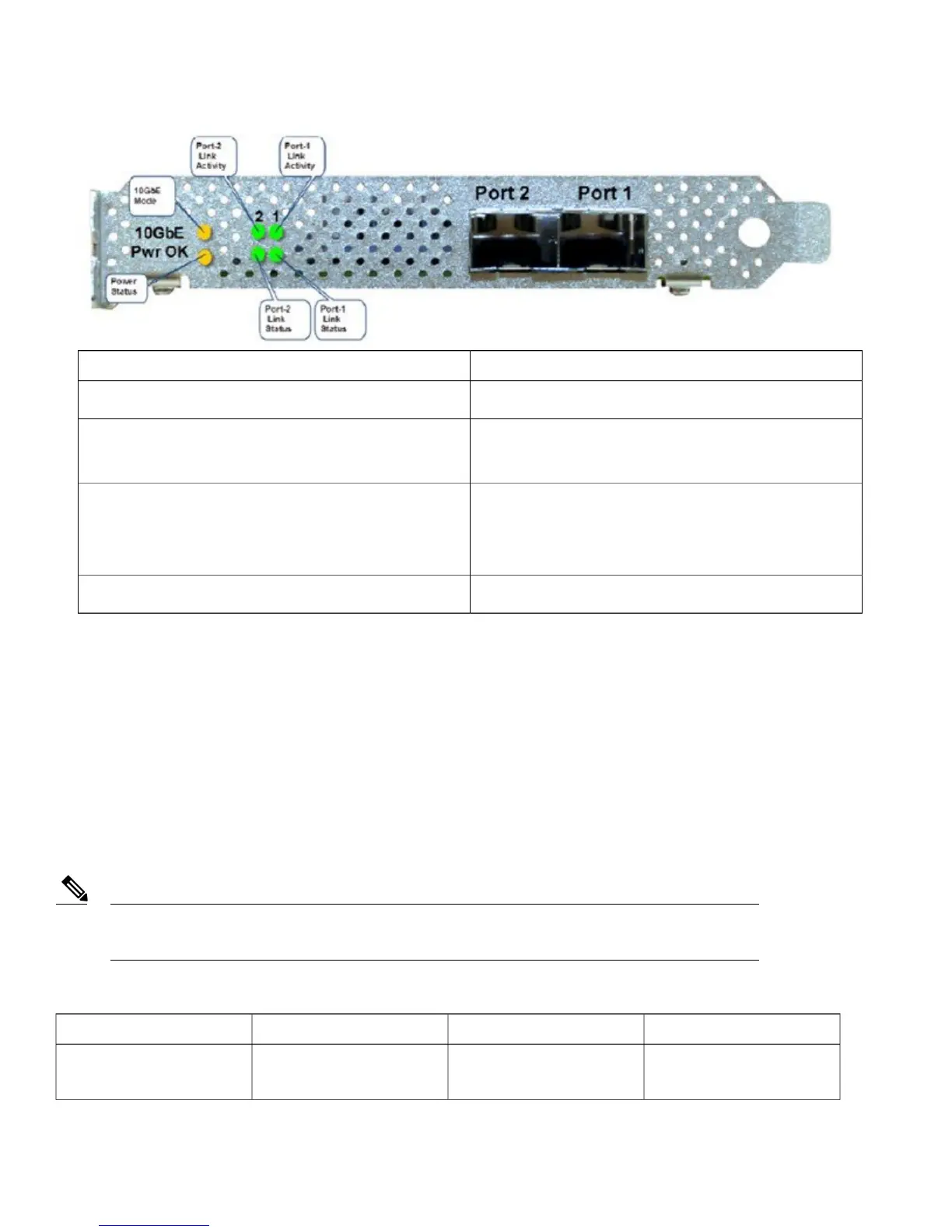
Functional DefinitionLED
LED: (Amber) On indicates power is goodPwr OK
LED: (Amber) On indicates 10 G mode
LED: Off indicates 1 G mode
10 G
Green On—Link is up in 10Gbe Mode
Amber On—Link is up in 1 Gbe Mode
Off—Link status is down
Port-n Link Status
LED: (Green) blinking indicates link activityPort-n Link Activity
Switching Between 10 G and 1 G
•
If there is nothing installed in port 1, the board will be configured for 10 G mode by default. Therefore, to switch to 1 G mode,
an SFP module must be installed in port 1 and the system needs to be rebooted.
•
Conversely, if an SFP module is installed and the user wants to switch to 4 x 10 G mode, then an SFP+ module must be installed
in port 1 and the WLC rebooted.
•
Thus, Online Insertion and Removal (OIR) of SFP and SFP+ between 10 G and 1 G is not possible.
•
OIR of 10 G to 10 G and 1 G and 1 G is possible.
It is recommended to have all ports as either 10 G or 1 G. In case they are different, port 1 SFP determines
the mode of operation and functionality on the other SFPs may not work.
Note
Table 9: Functionality of Cisco 5520 WLC when OIR occurs
RemarksPort2Port1Hot Swap of SFP/SFP+
Cisco 5520 WLC requires
reboot for Port1 OIR in 1G
YesNo1G to 1G
14