3-6
Cisco Network Convergence System 6000 Series Routers Hardware Installation Guide
OL-29234-02
Chapter 3 Installing the Exterior Cosmetics
Installing the Front Exterior Cosmetics
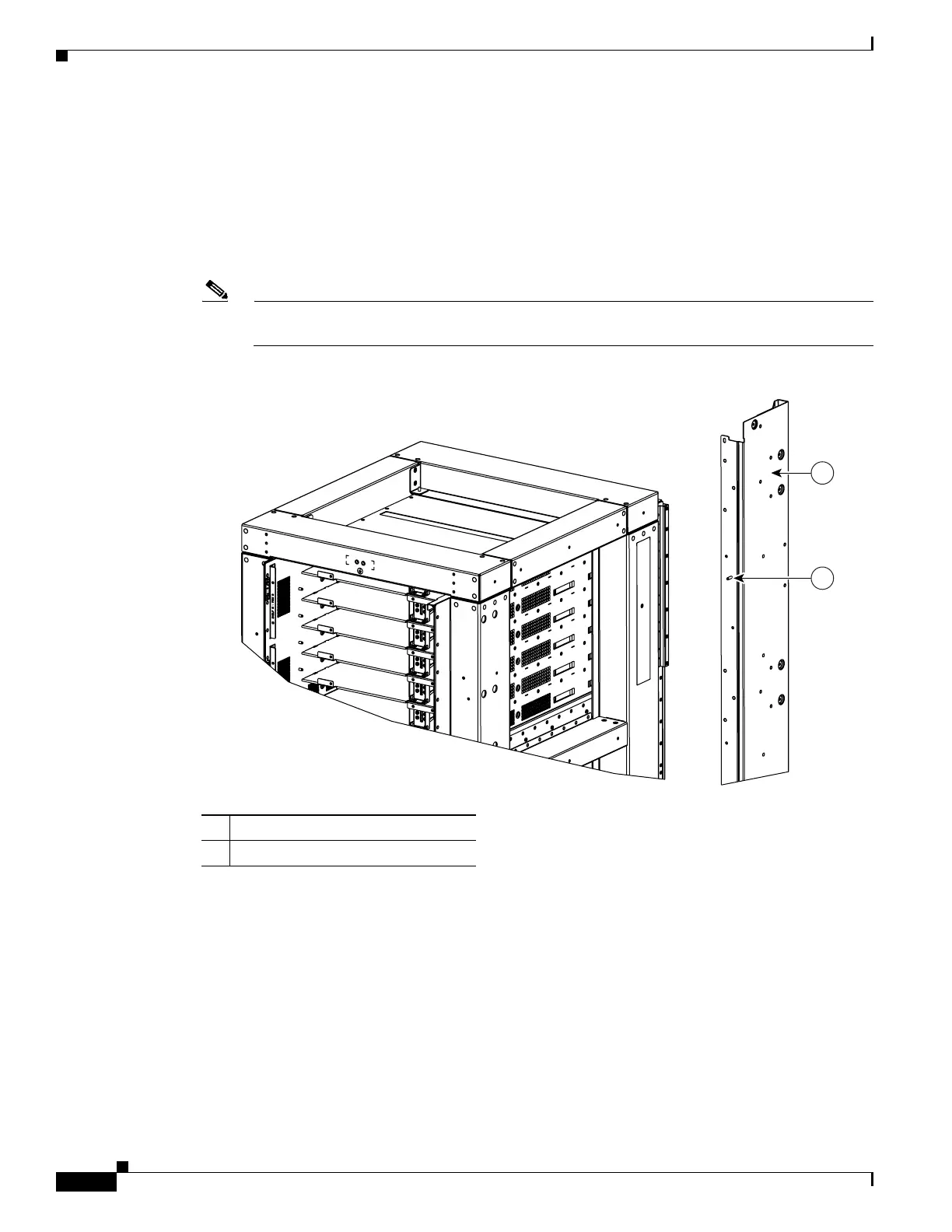
Step 2 Attach the left and right vertical cable troughs to the front of the chassis (Figure 3-3). The two vertical
cable troughs are inverted from each other. For each vertical cable trough:
a. Align the guide pins on the rear of the vertical cable trough with the positioning holes on the front
of the chassis (Figure 3-4).
b. Loosely insert eight pan-head screws, and then use the screwdriver to tighten them clockwise to
attach the vertical cable troughs firmly to the front of chassis. You might need to use a ladder to
reach the upper screws.
Note We recommend that you use two people to attach the vertical cable troughs; one person to hold
the vertical cable troughs in place while the other person inserts and tightens the screws.
Figure 3-4 Vertical Trough with Guide Pins
Step 3
Attach the front cable management brackets (Figure 3-3).
a. Attach the upper horizontal bracket (above the LC cage) by inserting and tightening four pan-head
screws.
b. Attach the lower horizontal brackets (below the LC cage) by inserting and tightening five pan-head
screws.
Step 4 Attach the front door alignment bracket to the chassis above the craft display panel by inserting and
tightening two pan-head screws along with tightening the captive screw (Figure 3-3).
Step 5 Attach the door hinge attachments, three left and three right, using two pan-head screws each
(Figure 3-5).
390409
1
2
1 Vertical cable trough
2 Guide pin
 Loading...