Do you have a question about the Cisco NCS-57B1-6D24-SYS and is the answer not in the manual?
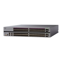
Provides an overview of the Cisco NCS 5700 series fixed-port routers.
Lists and describes the components that can be replaced in the field.
Details the function and characteristics of the route processor card.
Explains the types and functionality of Modular Port Adapters (MPAs).
Describes the physical network interfaces on the routers.
Information on supported transceivers and optical cables.
Essential safety precautions and warnings for equipment installation.
General instructions for mounting the chassis into an equipment rack.
Specific procedure to mount the NCS-57B1 in a 2-post rack.
Specific procedure to mount the NCS-57C3-MOD in a 2-post rack.
Instructions for properly grounding the router chassis.
Steps for connecting the chassis to an AC power source.
Steps for connecting the chassis to a DC power source.
Procedure for establishing a console connection for management.
Steps to perform the initial configuration of the router.
General instructions for installing and removing transceiver modules.
Procedures for replacing power supply units.
Steps to replace the route processor card.
Commands to verify the installation and configuration of the device.
| Product Type | Router |
|---|---|
| Model | NCS-57B1-6D24-SYS |
| Form Factor | Modular |
| Rack Units | 2RU |
| Total Ports | 24 |
| Memory | 32 GB |
| Flash Memory | 64 GB |
| Cooling | Front-to-back airflow |
| Power Supply | AC or DC |
| Operating System | Cisco IOS XR |