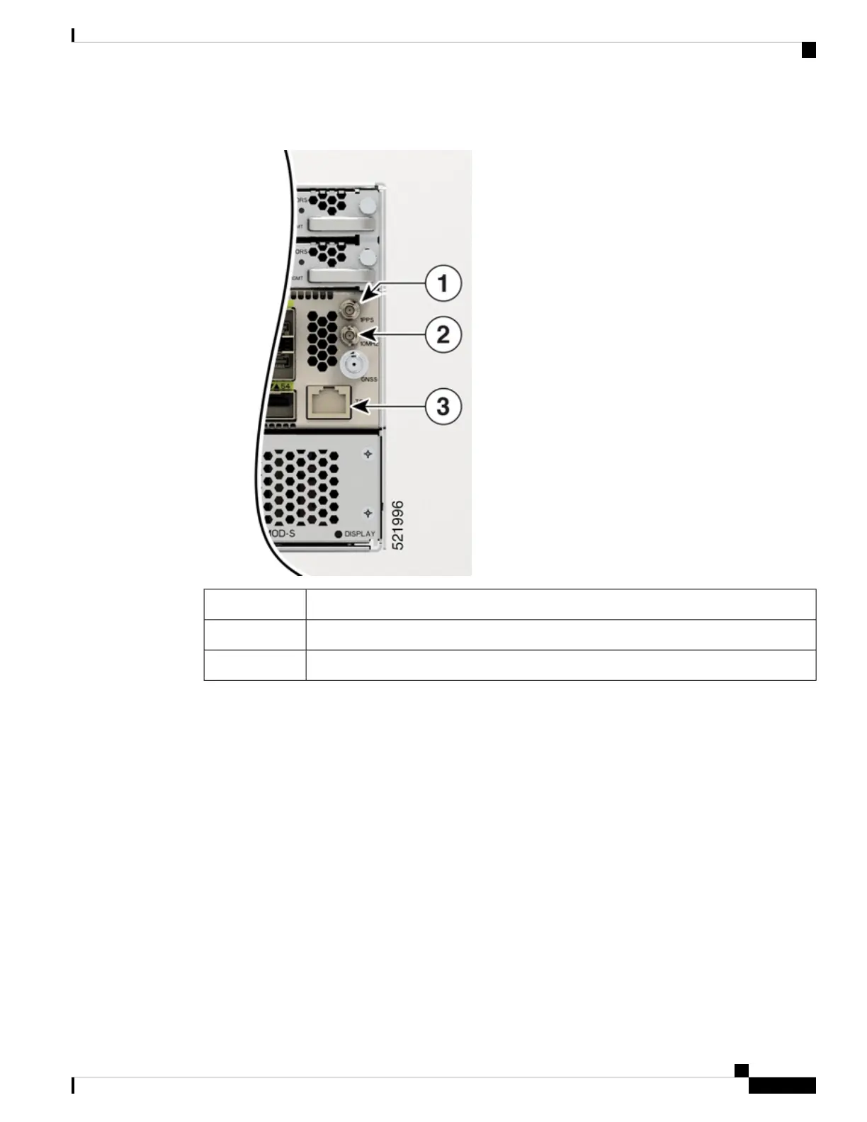
Figure 13: NCS-57C3-MOD - Network Timing Interfaces
1PPS port1
10MHz port2
ToD port3
The same RS422 pins for 1PPS and TOD are shared between input and output directions. The direction for
each can be independently configurable through software.
Use an SMB connector of type DIN 1.0/2.3 on the front panel for the following:
• GPS 10Mhz input and output—10MHz input for GPS Synchronization.
• GPS 1 PPS input and output—1 PPS input for GPS Synchronization.
GNSS
The GNSS port is present on the front panel.
GNSS module has an in-built ESD protection on all pins, including the RF-input pin. However, additional
surge protection is required if an outdoor antenna is being connected. The Lightning Protector must support
a low clamping voltage (less than 600V).
Hardware Installation Guide for Cisco NCS 5700 Series Fixed-Port Routers
15
NCS 5700 Router Overview
GNSS