Do you have a question about the Cisco NCS 5700 Series and is the answer not in the manual?
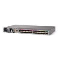
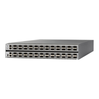
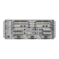
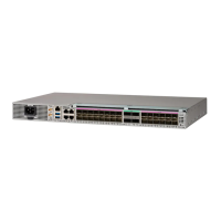
Overview of the Cisco NCS 5700 series fixed-port routers for aggregation, distributed core, and peering.
Details on the Field Replaceable Units (FRUs) supported by the NCS 5700 series fixed-port routers.
Information about route processor cards managing routing operations on the NCS-57C3-MOD router.
Details on modular port adapters (MPAs) supported on NCS-57C3-MOD routers and their LEDs.
Hardware features of the NCS-57B1 and NCS-57C3-MOD routers regarding network interfaces.
Information on physical specification, temperature, and Route Processor for all variants.
Details on 1PPS input/output and ToD input/output via RJ-45 interface.
Information on the GNSS port and its functionality on the NCS 5700 series routers.
Description of the RS232 console port for transmission, reception, and ground.
Details on the router's support for Online Insertion and Removal (OIR) for modules.
Guidance on determining supported transceivers and cables via compatibility tools.
Workflow overview for installing Cisco NCS 5700 series chassis and components.
Safety guidelines to prevent injury and equipment damage during installation procedures.
NEBS GR-1089-CORE cautions and regulatory compliance statements for equipment.
Guidelines to ensure proper site preparation for chassis installation and operation.
Required front and rear clearance for chassis airflow, removal, and installation of modules.
Guidelines for ensuring proper airflow by positioning the router in cold and hot aisles.
List of necessary tools and equipment for installing the Cisco NCS 5700 chassis.
Information on accessory kit PIDs and items for fixed port routers.
Illustrates how the building housing the chassis must be properly grounded to earth ground.
Instructions on how to prepare yourself (ESD protection) before handling the chassis.
Steps for installing the Cisco NCS 5700 series chassis into a standard 19-inch, four-post rack.
Details on rack specifications and types compatible with the Cisco NCS 5700 series chassis.
Procedures for mounting the NCS-57B1 and NCS-57C3-MOD chassis on 2-post or 4-post racks.
Step-by-step instructions for properly grounding the chassis for safety and compliance.
Procedures for connecting AC power to the NCS 5700 series router chassis.
Instructions for connecting DC power to the NCS 5700 series router chassis.
Summary of input and output power ranges for PSU low line and nominal applications.
Guidelines for connecting chassis ports using QSFP+, QSFP28, SFP28, and RJ-45 connectors.
Procedure to create a local management connection via a console terminal.
Steps to assign an IP address and configure the router management interface for network connectivity.
Instructions for connecting the management Ethernet port for out-of-band management.
Instructions for installing and removing SFP28, SFP+, QSFP-DD, and QSFP+/QSFP28 transceivers.
How to connect optical interface ports on line cards with other devices for network connectivity.
Steps to connect a shielded coaxial cable to the GNSS RF IN port and GNSS antenna.
Maintenance guidelines for transceivers and fiber-optic cables to ensure signal accuracy.
Procedures for removing and installing fan modules for NCS-57B1 and fan trays for NCS-57C3-MOD.
Information on the two different types of power supplies for the router and their replacement.
Steps for replacing the active or standby route processor (RP) cards in the router.
Step-by-step instructions for removing and installing modular port adapters (MPAs) on the router.
Using `show` commands to verify the installation and configuration of the router.
Location and description of STATUS, ALARM, SYNC, FAN, POWER, and GNSS LEDs on the chassis.
Description of STS, ACT, ATTN, and Management port LEDs on the route processor card.
Description of bi-color LEDs for data path connectivity through optical modules.
How the NCS-57C3-MOD front panel LED display shows the status of the ports.
Location and description of STATUS and ATTN LEDs on the Modular Port Adapter (MPA).
Location and description of Port Activity and Port Link LEDs for the management port.
Location of the LED on NCS-57B1 fan modules and NCS-57C3-MOD fan trays.
Location of the Status LED on the power supply modules for NCS 5700 routers.
Information on physical specifications and power consumption from data sheets.
Information on environmental specifications from data sheets.
Description of RJ-45 connectors and their compatibility with network cables.
Summary of Management Ethernet port pinouts.
Summary of ToD/1-PPS port pinouts.
Summary of USB flash or MEM port pinouts.
Summary of Console port pinouts.
Information on supported power cables from data sheets.
| Series | NCS 5700 |
|---|---|
| Product Type | Router |
| Operating System | Cisco IOS XR |
| Dimensions | Varies by model |
| Weight | Varies by model |
| Product Family | NCS |
| Category | Routers |
| Form Factor | Chassis |
| Rack Height | 1U, 2U, 4U |
| Supported Interfaces | Ethernet, Optical |
| Port Density | Varies by model (high-density options available) |
| Routing Protocols | BGP, OSPF, IS-IS, EIGRP |
| Power Supply | AC or DC |
| Power Supply Options | Redundant power supplies |
| Redundancy | Power supply redundancy, fan redundancy |
| Cooling | Front-to-back and back-to-front airflow |
| Management | CLI, SNMP |
| Management Interfaces | Ethernet |
| Environmental Conditions | Operating temperature: 0 to 40°C |






 Loading...