2 Cisco 7000 and Cisco 7507 Air Filter and Chassis Blower Replacement Instructions
Product Overview
Product Overview
This section provides brief physical and functional descriptions of the chassis blower and air filter.
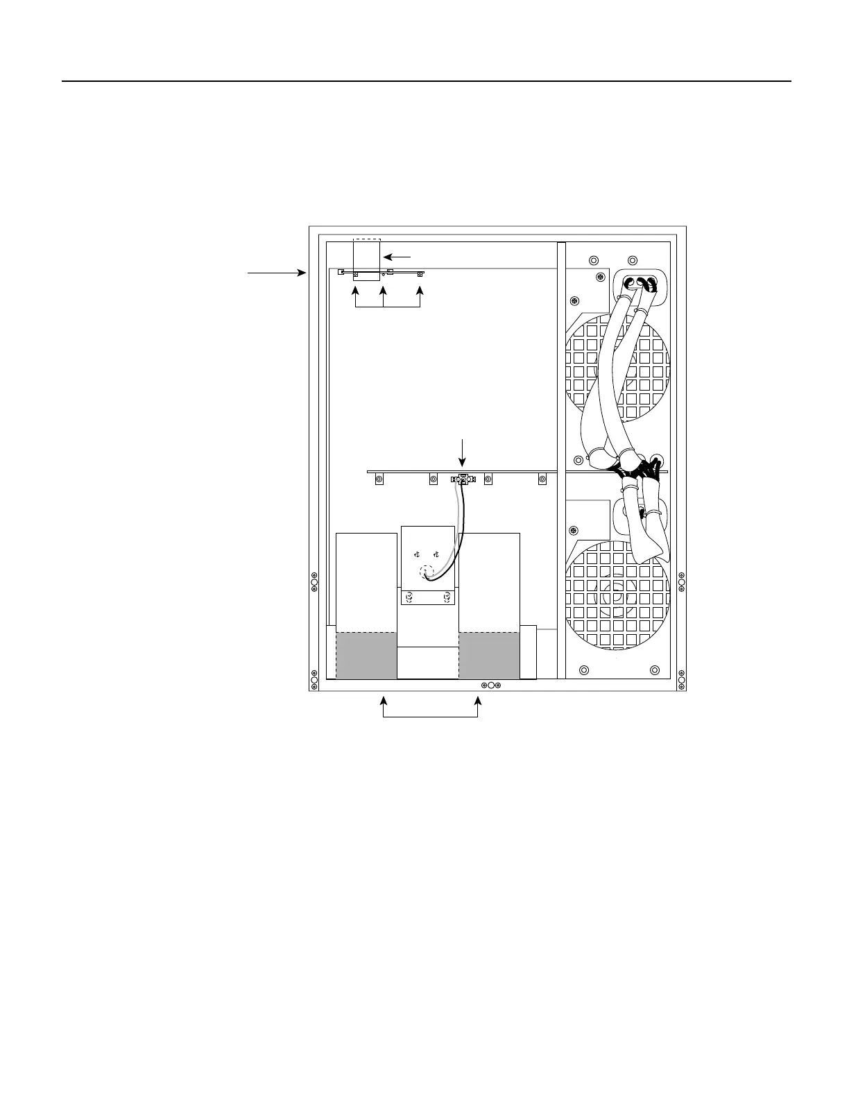
shows the front of the chassis with the top and bottom front panels removed to show the internal
components.Internal Chassis Front View
The system blower provides cooling air for the chassis internal components. The blower is located
on the bottom left of the chassis interior when viewed in the orientation shown in . The blower draws
air in through the air filter (which is not shown in ) and directs it up through the floor of the internal
card cage and over the processor modules. The exhaust air is forced out the rear of the chassis above
and to each side of the internal slot compartment. The airflow path is shown in Figure 1. The air dam
shown in Figure 1 keeps the chassis blower air separate from the air drawn in by the power supply
fans. A cable (purple +24V wire and black ground wire) with a keyed three-prong plug connects the
blower to the backplane power bus to deliver power from the power supplies. (See the blower power
connection in .)
Two air ducts on the rear of the blower, shown shaded in Figure 1, fit snugly into the two cutouts in
the backplane. The blower is secured to the backplane with three large captive Phillips or Allen-head
screws. (The earliest chassis manufactured use Phillips screws; the rest now use Allen-head screws.)
H3898
LED board
(mounted on horizontal
plane in chassis)
LED board spring
LEDs
Blower air ducts to
interface processor
compartment
Blower connection