B-4
Cisco 7600 Series Router Supervisor Engine and Route Switch Processor Guide
OL-10100-04
Appendix B Cable and Connector Specifications
Uplink Port Transceiver Modules
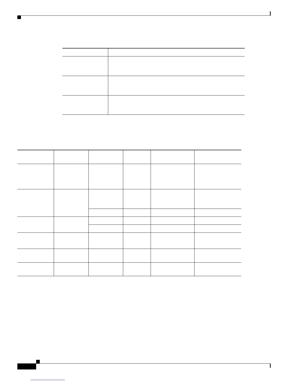
Table B-3 lists the cabling specifications for the 1GE uplink ports, which are located on SFP transceiver
modules that plug into the front panel.
SFP-GE-S 1000BASE-SX SFP transceiver module for MMF,
850-nm wavelength, extended operating temperature range and
DOM support, LC connector
SFP-GE-L 1000BASE-LX/LH SFP transceiver module for MMF and SMF,
1300-nm wavelength, extended operating temperature range and
DOM support, LC connector
SFP-GE-T 1000BASE-T SFP transceiver module for Category 5, 5e, or 6
copper wire, extended operating temperature range and DOM
support (NEBS 3ESD); 10/100/1000-Mbps RJ-45 connector
Table B-2 1GE SFP Transceiver Modules (continued)
Product ID Description
Ta b l e B-3 1GE Cabling Specifications
SFP Module
(Product ID)
Wavelength
(nm)
Fiber Type
(MHz km)
Core Size
(micron)
Modal Bandwidth
(MHz km)
Maximum Cable
Distance
GLC-SX-MM
SFP-GE-S
850 MMF
1
1. Multimode fiber (MMF) only.
62.5
62.5
50
50
160
200
400
500
722 ft (220 m)
902 ft (275 m)
1640 ft (500 m)
1804 ft (550 m)
GLC-LH-SM
SFP-GE-L
1300 MMF
2
2. A mode-conditioning patch cord is required when using the GLC-LH-SM module with 62.5-micron diameter MMF for link distances
greater than 984 ft (300 m). In addition, we do not recommend using the GLC-LH-SM module and MMF without a patch cord for very
short link distances (tens of meters) because it may result in an elevated bit error rate (BER).
Install the patch cord between the module and the MMF cable on both the transmit and receive ends of the link. For more information
about the patch cord, see the “Mode-Conditioning Patch Cord Description” section of the document at the following URL:
http://www.cisco.com/en/US/products/hw/routers/ps341/prod_module_installation_guide09186a00801cc731.html#wp29618
62.5
50
50
500
400
500
1804 ft (550 m)
1804 ft (550 m)
1804 ft (550 m)
SMF
3
3. ITU-T G.652 SMF as specified by the IEEE 802.3z standard.
9/10 — 6.2 mi (10 km)
GLC-ZX-SM 1550 SMF 9/10 — 43.5 mi (70 km)
SMF
4
4. Dispersion-shifted single-mode fiber-optic cable.
8 — 62.1 mi (100 km)
GLC-T
SFP-GE-T
— Cat 5, 5e, or 6
copper wire
— — 328 ft (100 m)
GLC-BX-D 1490-nm TX
1310-nm RX
SMF
3
— — 6.21 mi (10 km)
GLC-BX-U 1310-nm TX
1490-nm RX
SMF
3
— — 6.21 mi (10 km)

 Loading...


