B-14
Cisco 7600 Series Router Supervisor Engine and Route Switch Processor Guide
OL-10100-04
Appendix B Cable and Connector Specifications
Fiber-Optic Connectors
Make sure that you insert the connector completely into the socket. This action is especially important
when you are making a connection between a module and a long distance (1.24 miles [2
kilometers]) or
a suspected highly attenuated network. If the LINK LED on the supervisor engine or route switch
processor does not light, try removing the network cable plug and reinserting it firmly into the module
socket. It is possible that enough dirt or skin oils have accumulated on the plug faceplate (around the
optical-fiber openings) to generate significant attenuation, reducing the optical power levels below
threshold levels so that a link cannot be made.
Caution Use extreme care when removing or installing connectors so that you do not damage the connector housing
or scratch the end-face surface of the fiber. Always install protective covers on unused or disconnected
components to prevent contamination. Always clean fiber connectors before installing them.
For fiber-optic connector cleaning instructions, see the “Cleaning the Fiber-Optic Connectors” section
on page B-15.
When you disconnect the fiber-optic cable from the module, grip the body of the connector. Do not grip
the connector jacket-sleeve. Gripping the sleeve can, over time, compromise the integrity of the
fiber-optic cable termination in the MT-RJ connector.
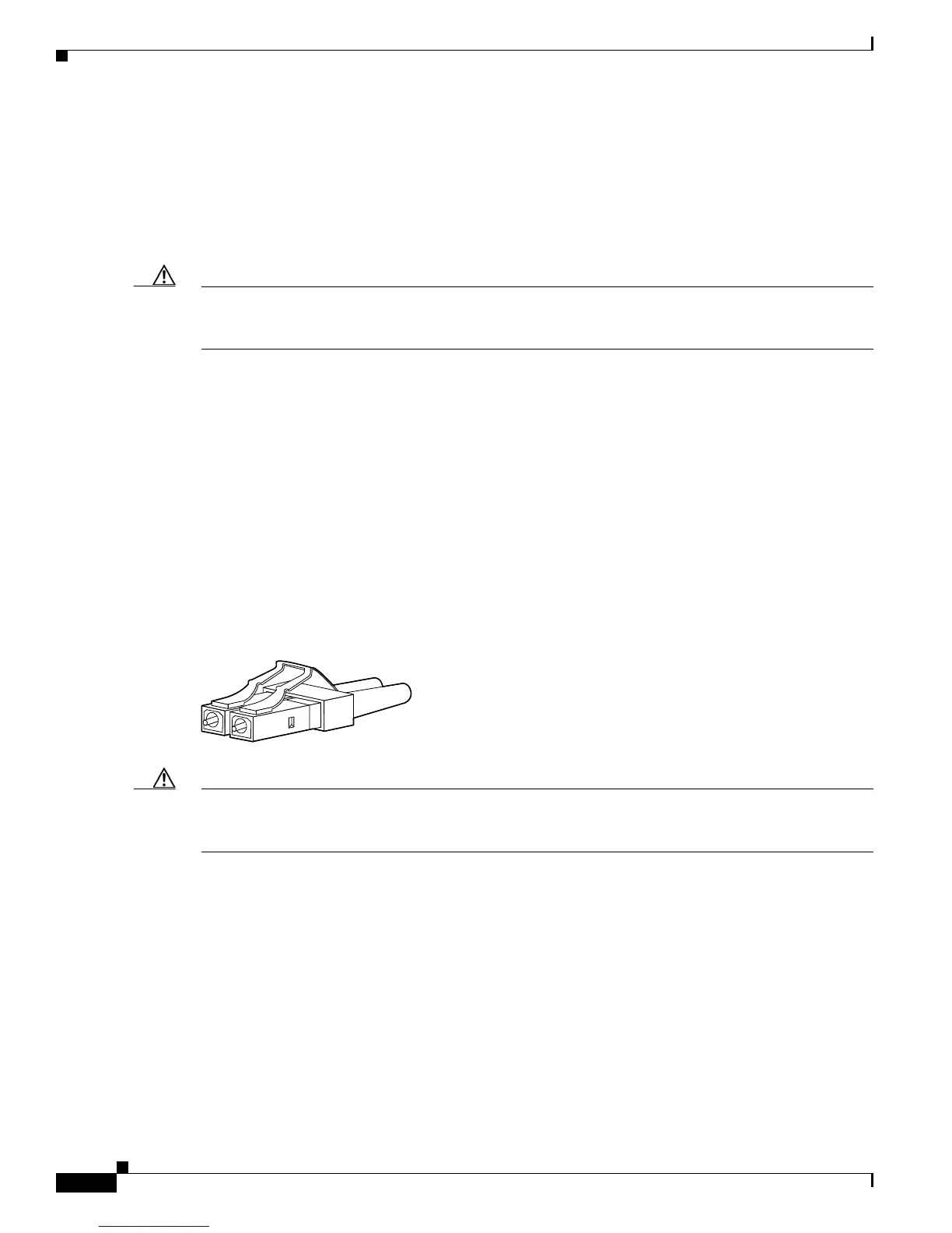
LC Connectors
The small form-factor pluggable (SFP) tranceiver modules used on the Supervisor Engine 720, Route
Switch Processor 720, and RSP720-10GE uplink ports use either MT-RJ connectors or LC connectors
depending on the SFP module vendor.
Figure B-7 shows an LC connector.
Figure B-7 LC Fiber-Optic Connector
Caution Use extreme care when removing or installing connectors so that you do not damage the connector housing
or scratch the end-face surface of the fiber. Always install protective covers on unused or disconnected
components to prevent contamination. Always clean fiber connectors before installing them.
For fiber-optic connector cleaning instructions, see the “Cleaning the Fiber-Optic Connectors” section
on page B-15.
When you disconnect the fiber-optic cable from the module, grip the body of the connector. Do not grip
the connector jacket-sleeve. Gripping the sleeve can, over time, compromise the integrity of the
fiber-optic cable termination in the LC connector.
58476

 Loading...


