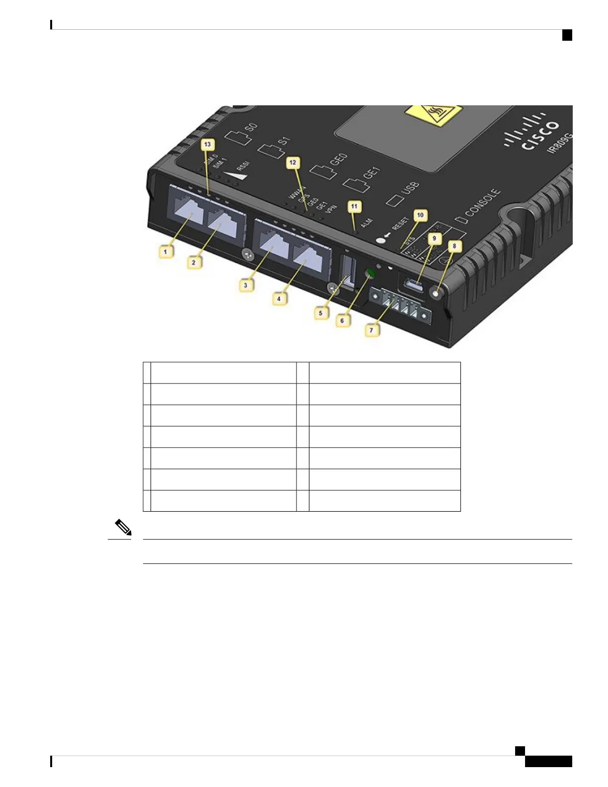
Figure 2: Cisco IR809 Front Panel
Grounding Point8S0 RS232 DCE/RS485 Combo Port1
Mini type-B USB console/debug port9S1 RS232 DTE only2
SYS LED10GE0 (10/100/1000)3
Alarm LED11GE1 (10/100/1000)4
WAN/WWAN LEDs12USB 2.0 (Type-A Host Port)5
SIM Card LEDs13RESET Button6
DC Power/Alarm Connector7
LEDs are viewable from the top and from the front of the IR809.
Note
The following figure shows the back panel details of the Cisco IR809.
Cisco 809 Industrial Integrated Services Router Hardware Installation Guide
3
Product Overview
General Description