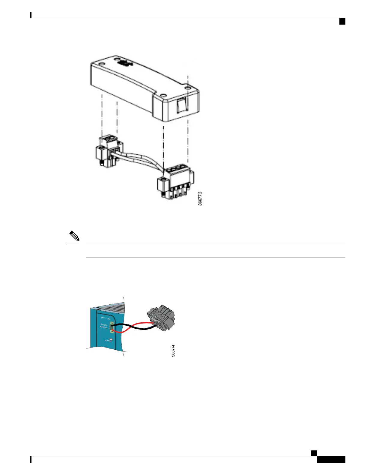
Dispose of the cover and the wire in the pre-assembled cable clip, but keep the 2-pin connector for the power
supply side, and the 4-pin connector for the IR809 side.
The IR809 should already have this 4-pin connector included, but if not, the one in the clip can be used.
Note
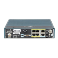
Measure an appropriate length of wire for your installation and wire the 2 pin connector back onto the
PWR-IE50W-AC power source DC output as it was. Wire the opposite end of the wire to the IR809 4 pin
connector as instructed previously in the Wiring the DC Power and Alarm Connections section. Your finished
cabling will look like the connectors and wiring in the bottom of the following figure:
The connections should match up as in the following table:
Cisco 809 Industrial Integrated Services Router Hardware Installation Guide
37
Connecting the Router
Connecting the Router to the DC Source.