3-4
Cisco 850 Series and Cisco 870 Series Access Routers Hardware Installation Guide
OL-5331-01
Chapter 3 Router and PoE Module Mounting Procedures
Mounting on a Wall
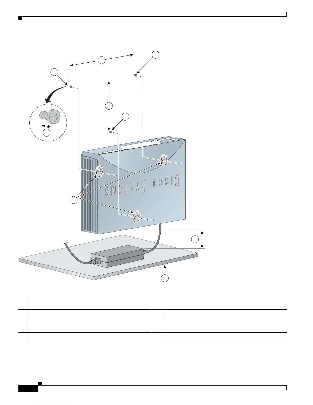
Figure 3-2 Mounting the Router on a Wall
1 Three number-six, 3/4 in. screws 5 Maximum distance between the router and the power
adapter (6 ft. [1.8 m])
2 Distance between the top set of screws on the wall 6 Horizontal surface on which to place the power adapter
3 Vertical distance between the top screws and the bottom
screw on the wall
7 Distance between the screw head and the wall (1/8 in.
[0.32
cm])
4 Mounting brackets
O
K
L
N
K
P
P
P
V
P
N
O
K
D
A
T
A
W
L
A
N
R
X
D
W
A
N
T
X
D
CIS
CO
800 SE
RIES
ETHERNET LAN
0
1
2
3
121714
5
6
4
2
7
1
1
1
3
 Loading...