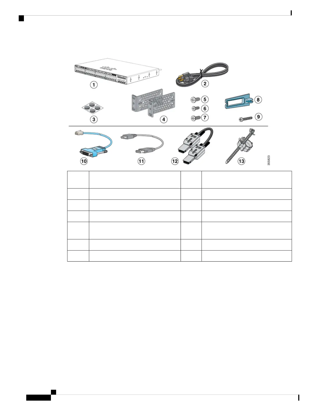
Figure 8: Components delivered in the shipping box
Cable guide8Cisco Catalyst 9200 Series switch
1
(power
supply modules are not displayed)
1
M4.0 x 20mm Phillips pan-head screw9AC power cord2
RJ-45 USB console cable
1
10Four rubber mounting feet3
(Optional) USB console cable
1
11Two 19-inch mounting brackets4
(Optional) StackWise cable
1
(0.5-meter,
1-meter, or 3-meter)
124 number-12 pan-head screw5
Power cord retainer134 number-10 pan-head screws6
--8 number-8 Phillips flat-head screws7
1. Item is orderable.
Tools and Equipment
Obtain these necessary tools:
• A Number-2 Phillips screwdriver.
Verifying Switch Operation
Before you install the switch in a rack or on a table or shelf, power on the switch and verify that it passes
POST.
To power on the switch, plug one end of the AC power cord into the switch AC power connector, and plug
the other end into an AC power outlet.
Cisco Catalyst 9200 Series Switches Hardware Installation Guide
18
Installing the Switch
Tools and Equipment
 Loading...