Do you have a question about the Cisco C9200L-24T-4X-A and is the answer not in the manual?
Lists and describes the available Cisco Catalyst 9200 Series switch models.
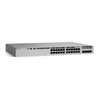
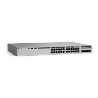
Details the components visible on the front panel of the switches.
Explains the capabilities and supported speeds of the multigigabit Ethernet ports.
Describes the different management ports available on the switch.
Details the function and usage of the USB Type A port for storage and upgrades.
Covers the types of uplink ports and supported transceiver modules.
Illustrates and describes the rear panel components of the switches.
Explains the built-in passive RFID tag for asset management and tracking.
Describes the StackWise ports used for connecting switches in a stack configuration.
Details the supported internal power supply modules and their specifications.
Describes the fan modules that provide cooling for the switch.
Details the Ethernet management port for connecting to a host.
Explains the RJ-45 console port connection for management.
Refers to the software configuration guide for network configuration concepts.
Covers prerequisites and initial steps before installing the switch.
Lists critical safety precautions to be followed during installation and operation.
Provides guidelines for proper installation to ensure optimal performance and safety.
Lists the items included in the shipping box for the switch.
Lists the necessary tools and equipment required for installation.
Details steps to verify the switch's operation after installation and powering on.
Guides on planning and configuring switch stacks for enhanced functionality.
Covers the procedures for physically mounting the switch in a rack or on a shelf.
Details how to connect switches together using StackWise ports for stacking.
Explains how to connect network devices to the switch's Ethernet ports.
Describes how to connect devices that use Power over Ethernet (PoE) and PoE+.
Step-by-step guide for installing a network module into the switch.
Crucial safety warnings specific to installing network modules.
Procedure for physically installing a network module into the switch slot.
Instructions on how to safely remove a network module from the switch.
Covers the installation and removal of SFP, SFP+, SFP28, and QSFP+ transceiver modules.
Guidelines for installing or replacing power supply modules safely and correctly.
Detailed procedure for installing or replacing an AC power supply module.
Provides an overview of the supported internal power supply modules for the switches.
Describes the fan modules that provide cooling and redundancy for the switches.
Step-by-step instructions for installing a fan module into the switch.
Guides on setting up and managing the switch via its web-based graphical interface.
Steps to establish a connection to the switch for initial configuration.
Procedure for creating user accounts to control access and permissions on the switch.
Explains how to configure the device automatically based on predefined site profiles.
Details settings that apply across the entire switch, such as VLANs and STP.
Guides on configuring network services like DHCP, NTP, DNS, and SNMP for the switch.
Explains how to configure Spanning Tree Protocol (STP) settings on the switch.
Instructions on configuring individual switch ports based on their role (uplink, downlink, access).
How to configure virtual terminal lines for remote access via Telnet or SSH.
Provides instructions for configuring the switch using the command-line interface (CLI).
Steps to install the necessary USB driver for Windows PCs connecting to the switch console.
Provides environmental operating ranges and physical dimensions of the switches.
Details the technical specifications for power supplies and fan modules.
Explains the purpose of the switch LEDs for monitoring activity and performance.
Describes the Console LED status and its meaning.
Explains the System LED status and its meaning for system operation.
Describes the MASTER LED status for stack master or standalone switch identification.
Details the STACK LED which indicates the sequence of member switches in a stack.
Explains the PoE LED status indicating PoE or PoE+ mode.
Describes how port LEDs display information based on the selected port mode.
Explains the Beacon LED used to indicate the switch needs attention.
Describes the status and meaning of the RJ-45 Console Port LED.
Explains the Fan LED indicators for fan status.
Describes the status LEDs for the uplink ports.
| Model | C9200L-24T-4X-A |
|---|---|
| Switching Capacity | 128 Gbps |
| Forwarding Capacity | 95.2 Mpps |
| Power Supply | Internal |
| DRAM | 4 GB |
| Flash | 4 GB |
| MAC Address Table Size | 32, 000 entries |
| VLAN IDs | 4094 |
| Operating System | Cisco IOS XE |
| Device Type | Switch |
| Ports | 24 |
| Uplink Ports | 4 |
| Power over Ethernet (PoE) | No |
| Stacking | Yes |
| Management | CLI, SNMP |