18 Cisco LAN Switching Configuration Handbook
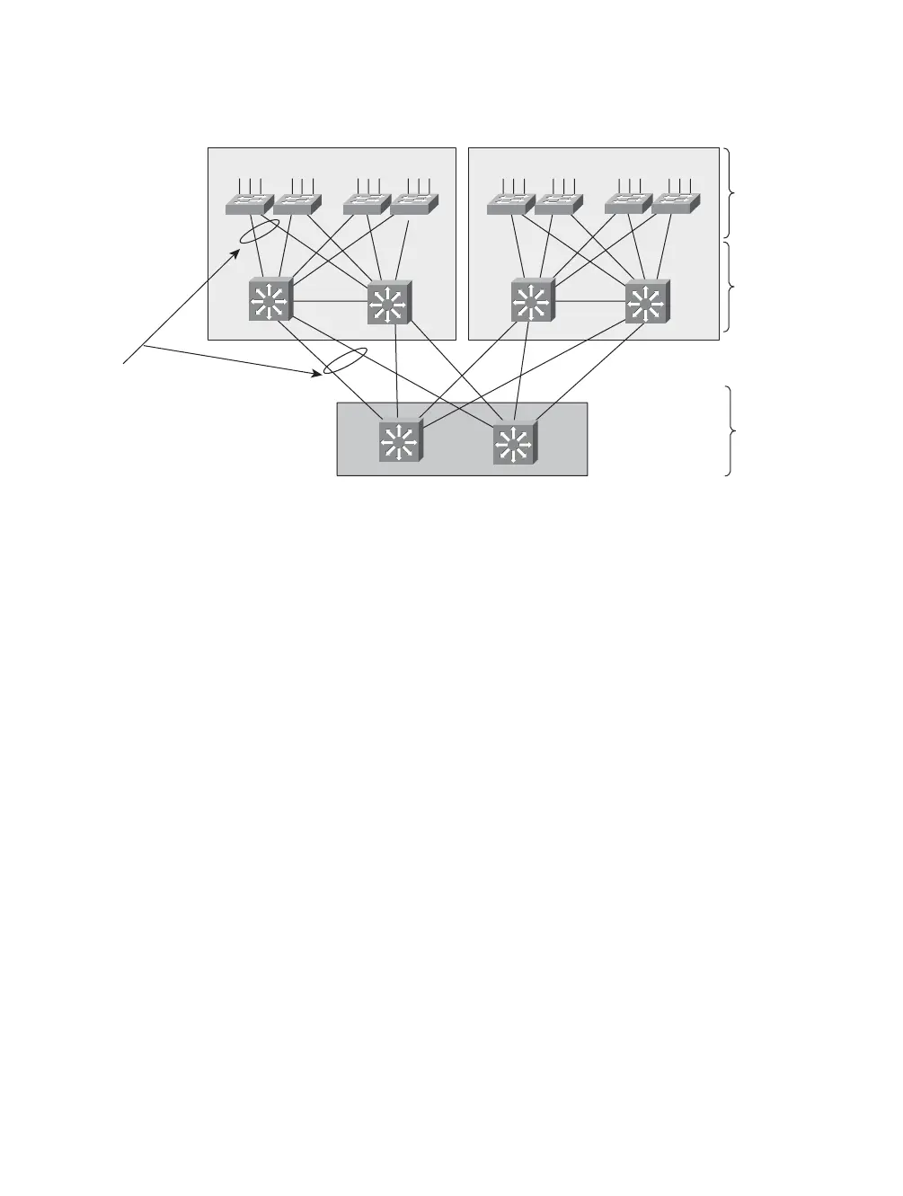
Switch Block 1
Switch Block 2
Core
Distribution
Access
Note the use of
dual redundant
uplinks into the
next-higher layer
for high
availability
Si
Si
Si
Si
Si
Si
Si
Figure 2-1 Layers of a Hierarchical Network Design
To provide high availability, each switch in a network layer needs to have dual or
redundant uplinks to two switches in the next higher layer. If a link failure or the fail-
ure of an entire switch occurs, the extra uplink can be quickly used. The uplink
failover is handled by the Spanning Tree Protocol (STP) at Layer 2 or by routing
protocols at Layer 3.
3. Place switching functionality at each layer of the hierarchy.
■ Access: Switches at this layer generally have a high port density, lower cost, fea-
tures that address user access or security, and several high-speed uplink ports.
Usually, Layer 2 switching is sufficient, although Layer 3 switching can provide
higher availability for applications such as IP telephony.
■ Distribution: Distribution switches have a port density consisting of high-speed
ports and offer higher switching performance, ideally at Layer 3.
■ Core: The core layer should be built from the highest performance switches in
the network, aggregating traffic from the distribution switches. Layer 2 switches
can be used effectively, although switching at Layer 3 adds higher availability
and enhanced QoS. Usually a dual-switch core layer is sufficient to support an
entire enterprise.
4. Identify resources in your network that serve common functions. These become the
modules or building blocks of your network design. Figure 2-2 shows some exam-
ples of these blocks and how they fit within the network hierarchy.