Building A Building Z
Switch
Blocks
WAN
Block
Server
Block
Core
Block
...
Mainframe
Block
Internet
Block
PSTN
Block
Si
Si
Si
Si
Si
SiSi
Si
Si
Si
V
V
V
V
Si
Si
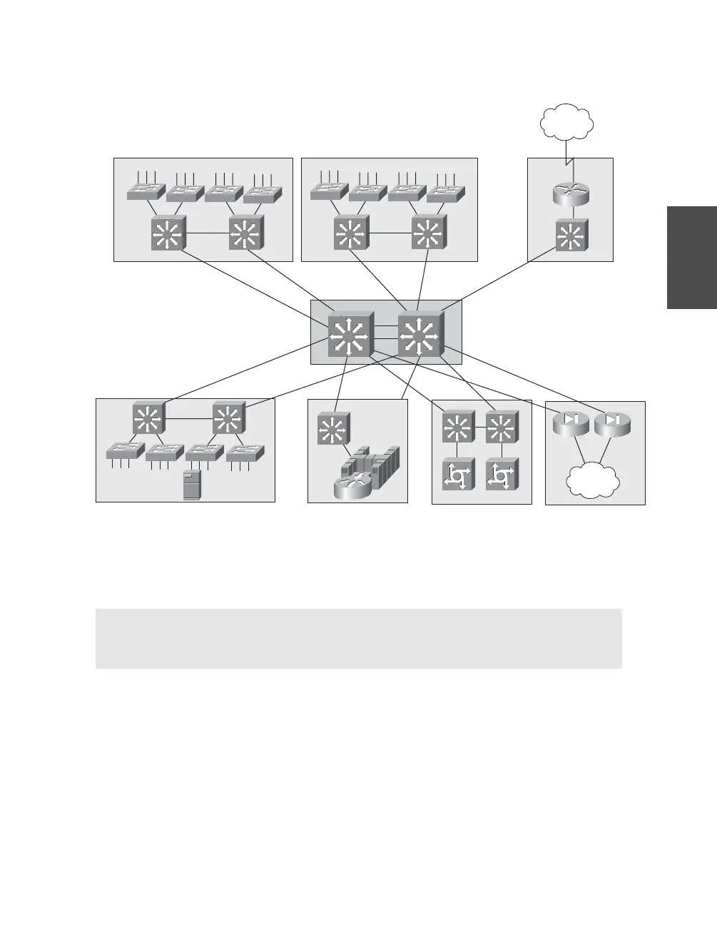
Figure 2-2 Modular Approach to a Campus Network Design Consider High Availability or
Redundancy Features That Can Be Used in Each Network Building Block
Chapter 2: Switch Functionality 19
Section 2-2
Tip The network in Figure 2-2 is shown with single uplinks to higher layers for simplicity.
In a real network, you need to always add dual redundant uplinks to two switches in the
next higher network layer for the highest network availability.
In this case, each access layer switch would have two uplinks to the two nearest distribution
switches. In addition, each distribution switch in each block of the diagram would have two
uplinks to the two core layer switches. In other words, the basic principles of Figure 2-1
need to be applied to the enterprise layout of Figure 2-2.
■ Server farms and mainframes: These are called server blocks and mainframe
blocks, respectively.
■ Internet access, e-commerce or extranet server farms, and firewall farms:
These are called an Internet block.