EasyManuals Logo

Cisco Catalyst 3750G User Manual

Cisco Catalyst 3750G
48 pages
To Next Page IconTo Next Page
To Previous Page IconTo Previous Page
Page #14 background imageLoading...
Page #14 background image
14
Step 12
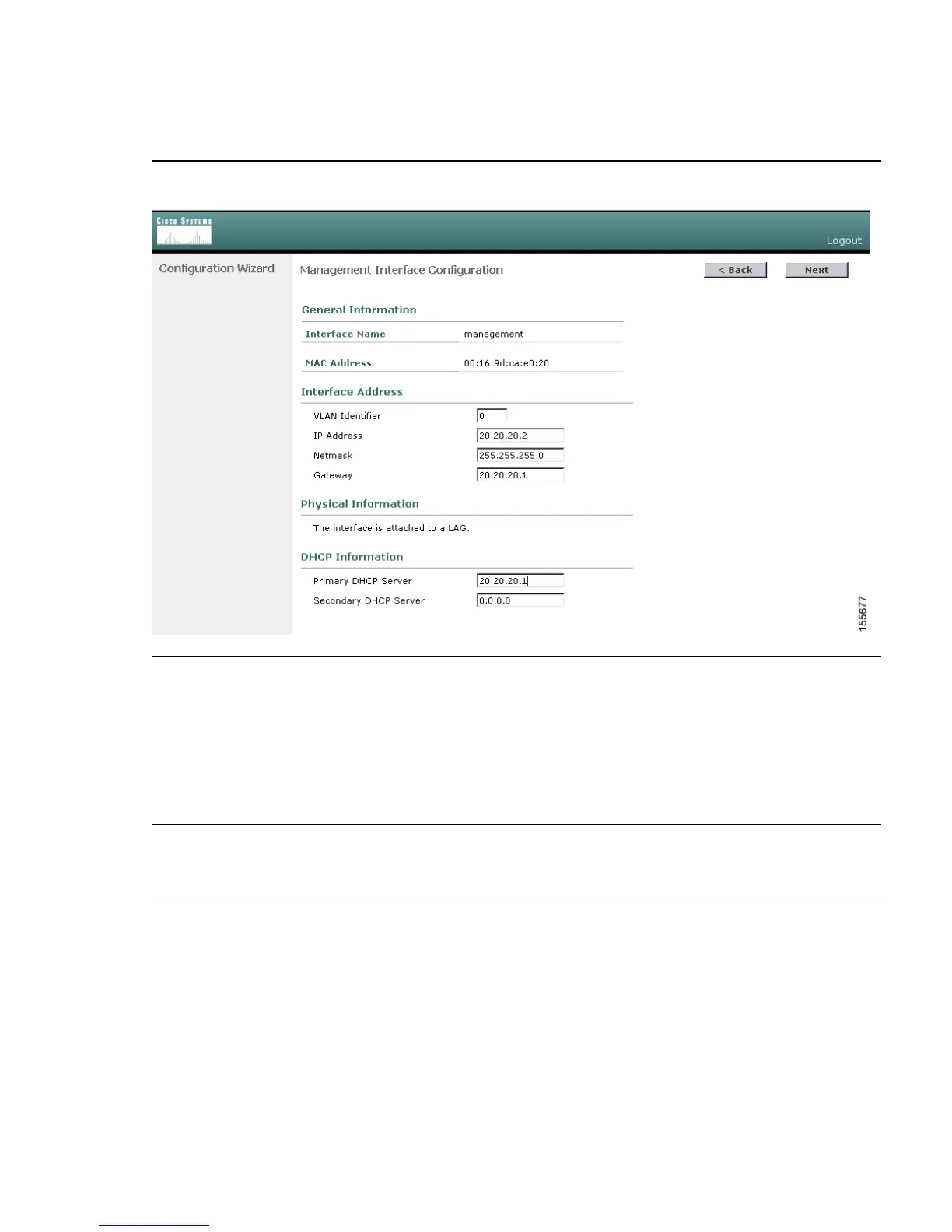
Click Next. The Management Interface Configuration page appears.
Step 13
Enter the VLAN identifier zero (0) if the VLAN ID set on the switch management interface
is 1. If you entered a VLAN ID other than 1 on the switch management interface (see Step
12 of the Running Express Setup section), enter the same VLAN ID for the controller.
Enter the IP address, the netmask, and the gateway for the management interface.
The management interface is the default interface for in-band management of the
controller and for connectivity to enterprise services such as authentication, authorization,
and accounting (AAA) servers.
Step 14
Enter the IP addresses of the primary and the optional secondary DHCP servers that
supply IP addresses to clients, the controller management interface, and, optionally, the
service-port interface.

Table of Contents

Questions and Answers:

Question and Answer IconNeed help?

Do you have a question about the Cisco Catalyst 3750G and is the answer not in the manual?

Cisco Catalyst 3750G Specifications

General IconGeneral
ModelCisco Catalyst 3750G
Switching Capacity32 Gbps
Forwarding Rate38.7 Mpps
Stacking Bandwidth32 Gbps
DRAM128 MB
Flash Memory16 MB
MAC Address Table Size12, 000 entries
VLANs1005
Operating Humidity10% to 85% non-condensing
Ports48 10/100/1000 Ethernet ports
Uplink Interfaces4 SFP Gigabit Ethernet ports
Jumbo FramesUp to 9216 bytes
Power SupplyAC
Operating Temperature0 to 45°C

Related product manuals