3-17
Catalyst 4948E and Catalyst 4948E-F Switch Installation Guide
OL-21561-02
Chapter 3 Installing the Switch
Attaching the Interface Cables
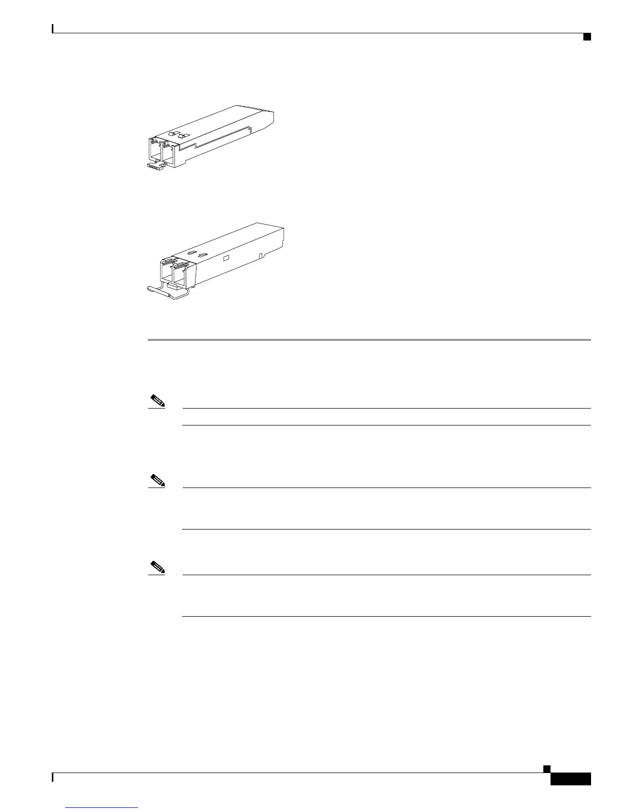
Figure 3-8 SFP Transceiver with an Actuator Button Latch
Figure 3-9 SFP Transceiver with a Bail-Clasp Latch
To install either an SFP or SFP+ transceiver, follow these steps:
Step 1 Attach an ESD-preventive wrist strap to your wrist and to the ESD ground connector or a bare metal
surface on your chassis.
Step 2 Remove the SFP transceiver from its protective packaging.
Note Do not remove the optical bore dust plugs until directed to do so later in the procedure.
Step 3 Check the label on the SFP transceiver body to verify that you have the correct model for your network.
Step 4 Find the send (TX) and receive (RX) markings that identify the top side of the SFP transceiver.
Note On some SFP transceivers, the TX and RX marking might be replaced by arrowheads pointing
from the SFP transceiver connector (transmit direction or TX) and toward the connector (receive
direction or RX).
Step 5 Position the SFP transceiver in front of the socket opening.
Note Different Cisco devices have different SFP socket configurations. Your Cisco device could have
either a latch-up or a latch-down orientation. Ensure that you are installing the SFP transceiver
in the correct orientation for your Cisco device.
Step 6 Holding it as shown in Figure 3-10, insert the SFP into the socket until you feel the connector latch into
place.