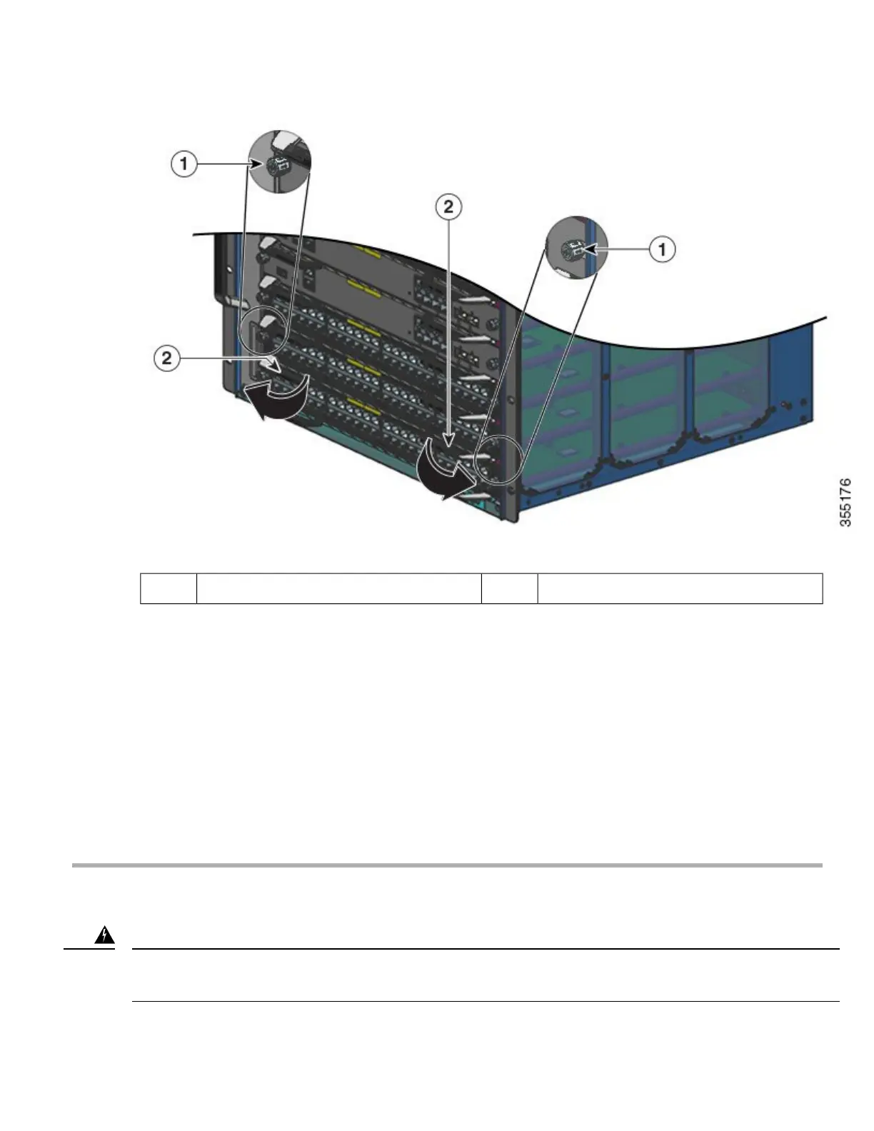
Ejector levers that must be pivoted out2Captive installation screws that must be loosened1
Step 5 Grasp the module front panel with one hand, and place your other hand under the module (on the metal carrier) to support
and guide it out of the slot. Do not touch the printed circuit boards or connector pins.
Step 6 Pull the module straight out of the slot, keeping one hand under the module to support it.
Step 7 Immediately place the removed module on an antistatic mat, in an antistatic bag, or install it in another slot.
Step 8 If the slot is to remain empty, install a blank module filler plate to keep dust out of the chassis, maintain proper airflow
through the chassis, preserve electromagnetic interference (EMI) integrity, and to prevent exposure to high current inside
the chassis.
Blank faceplates and cover panels serve three important functions: they prevent exposure to hazardous voltages
and currents inside the chassis; they contain electromagnetic interference (EMI) that might disrupt other
equipment; and they direct the flow of cooling air through the chassis. Do not operate the system unless all
cards, faceplates, front covers, and rear covers are in place. Statement 1029
Note
Installing the Switching Module
Hazardous voltage or energy is present on the backplane when the system is operating. Use caution when servicing. Statement
1034
Warning
25
 Loading...


