21
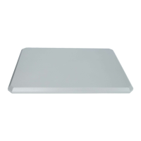
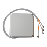
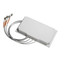
Cisco Catalyst 2.4 GHz and 5/6 GHz Dual-Band Polarization-Diverse Directional Patch Antenna (C-ANT9103=)
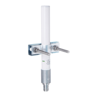
Mounting Directly on a Wall Through Mounting Holes on the Antenna
Note The fasteners and mounting surface should be capable of maintaining a minimum pullout force of 150
pounds (68 kg) to support the weight of the antenna along with the potential wind loading on the antenna.
Step 1 Determine the mounting location for the antenna.
Step 2 Mount the antenna to the wall using four 4 mm or #8 screws and fasteners, through the holes on the
antenna. See Figure 10.
Step 3 Orient the antenna correctly so that the antenna cable exits downwards.
Step 4 Place the cap plugs to cover the mounting holes on the antenna.
Step 5 Connect the antenna’s 8-DART plug to the access point.
For the recommended cable type, see the “Recommended Cable” section on page 26.
Figure 10 Exploded View of Antenna and Hardware Assembly for Direct Wall Mounting
1
Cap plugs.
3
One of four mounting holes on the antenna.
2
#8-18 stainless steel self tap screw.
4
#6-8, 1
1
/
4
-inch anchor.
 Loading...