15
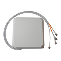
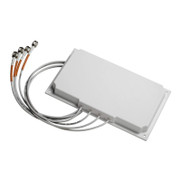
Cisco Catalyst 2.4 GHz and 5/6 GHz Dual-Band Polarization-Diverse Directional Patch Antenna (C-ANT9103=)
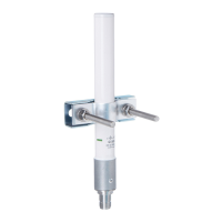
Mounting on a Wall or Ceiling Using Articulating Bracket
Note The fasteners and mounting surface should be capable of maintaining a minimum pullout force of 150
pounds (68 kg) to support the weight of the antenna along with the potential wind loading on the antenna.
Step 1 Determine the mounting location for the antenna.
Step 2 Attach the free articulating mount flange to the wall or ceiling using four 4mm or #8 screws and
fasteners, through the holes on the bracket.
Use one of the two articulating mount flange brackets (see Figure 1) that is included in the mounting kit.
Step 3 Assemble the bracket hardware, as shown in Figure 5. Use a wrench to tighten the
1
/
4
20 x 1.25" screws
on the brackets.
Step 4 Orient the antenna correctly so that the antenna cable exits downwards. Use a wrench to loosen or tighten
the fasteners at the azimuth and elevation- adjustment pivots.
Step 5 Adjust the azimuth (side-to-side position) and elevation (up-and-down position) of the antenna. Loosen
the adjustment pivot bolts slightly to allow for adjustment.
The azimuth angle can be adjusted ±60 degrees (Figure 8) and elevation can be adjusted ±60 degrees
(Figure 9). Use the azimuth and elevation markings on the articulating mounting arm and the flange
brackets as a guide. See Figure 7.
Step 6 After adjusting the antenna position, tighten the pivot bolts. Tighten all the bolts to not more than
30 lbf.in. (3.4 Nm).
Step 7 Connect the antenna’s 8-DART plug to the access point.
For the recommended cable type, see the “Recommended Cable” section on page 26.
 Loading...