25
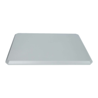
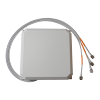
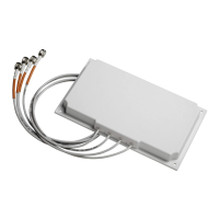
Cisco Catalyst 2.4 GHz and 5/6 GHz Dual-Band Polarization-Diverse Directional Patch Antenna (C-ANT9103=)
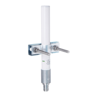
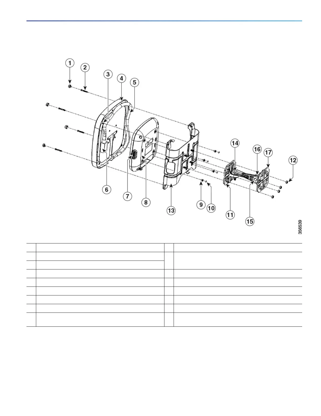
Figure 12 Exploded View of Bracket Hardware Assembly for Directly Mounting Access Point to Back of Antenna
1
Cap plugs.
10
Rubber feet.
2
#8-18 stainless steel self tap screw.
11
Articulating mount flange attached to the back of the
AIR-AP-BRACKET-9=.
3
Mounting holes on the antenna.
4
Antenna.
12
1
/
4
-20 serrated flange locknut.
5
Antenna’s octal DART cable.
13
AIR-AP-BRACKET-9=.
6
Antenna’s octal DART plug.
14
The azimuth adjustment pivot.
7
Access point’s octal DART port.
15
The elevation adjustment pivot.
8
Access point.
16
Mounting arm.
9
Shoulder screw.
17
Articulating mount flange bracket fixed to the mounting
surface.
 Loading...