Procedure
Step 1 Use a wire-stripping tool to remove approximately 0.75 inch (19 mm) of the covering from the end of the
grounding wire.
Step 2 Insert the stripped end of the grounding wire into the open end of the grounding lug.
Step 3 Crimp the grounding wire in the barrel of the grounding lug. Verify that the ground wire is securely attached
to the ground lug.
Step 4 Place the grounding wire lug against the grounding pad on the switch, making sure that there is solid
metal-to-metal contact.
Step 5 Before you secure the lug to the chassis, make sure that the grounding lug and the grounding wire do not
interfere with other switch hardware or rack equipment. Secure the grounding lug to the chassis with two
M4.0 x 8mm Phillips pan-head screws.
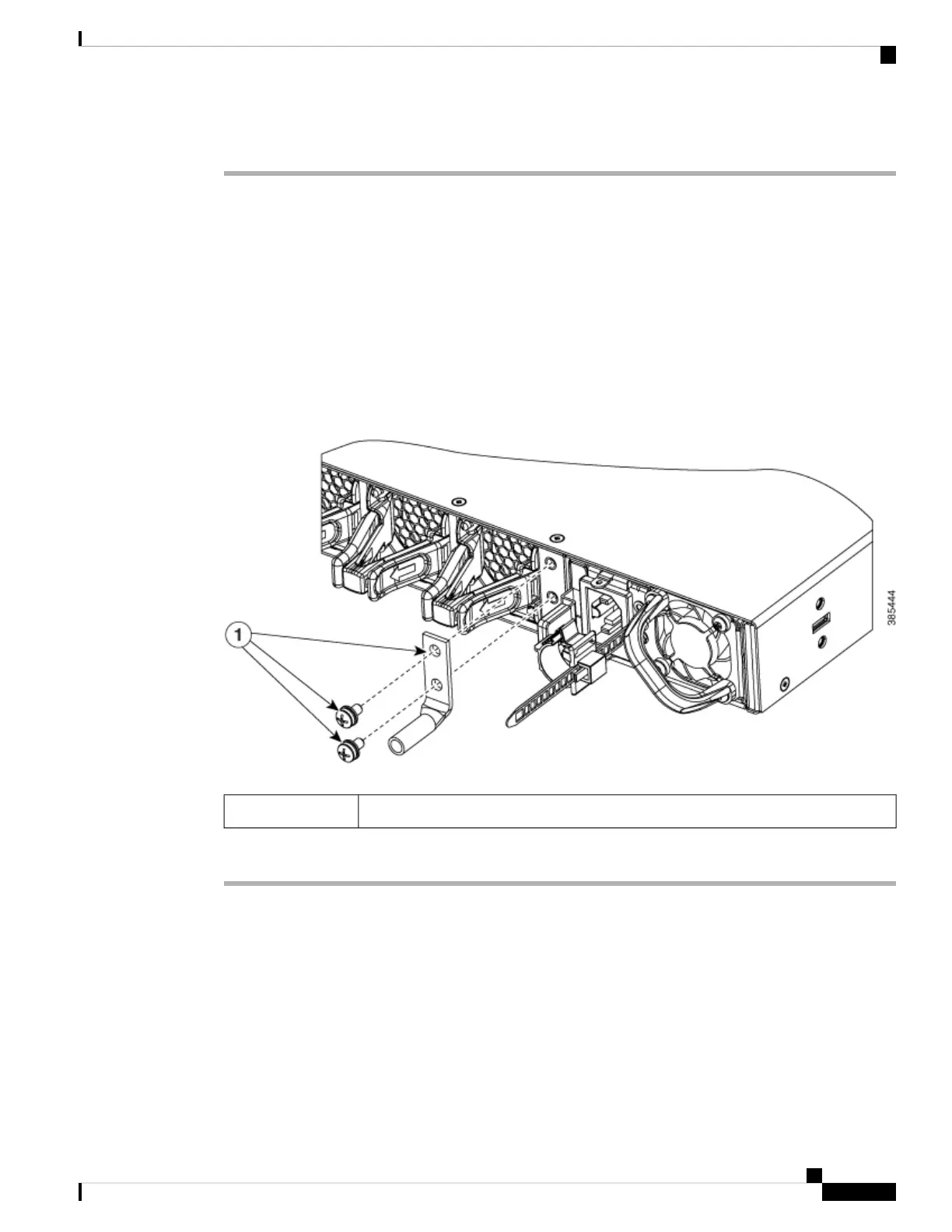
Figure 21: Connecting the System Ground
Ground lug and two M4.0x8mm Phillips pan-head screws1
Step 6 Prepare the other end of the grounding wire with a ring lug, and secure it to the rack with a screw.
Installing the Switch
Rack-Mounting
• For Network Equipment Building Systems (NEBS) installation, use the four post rack mount kit. The
depth of the rack, measured between the front-mounting and the rear-mounting strips must be:
• between 25.14 inches and 35.84 inches for C9500-24Q, C9500-12Q, C9500-40X and C9500-16X.
Cisco Catalyst 9500 Series Switches Hardware Installation Guide
41
Installing a Switch
Installing the Switch