Figure 4: Stripping the Power Connection Wire
0.25 in. (6.3 mm) ± 0.02 in. (0.5 mm)1
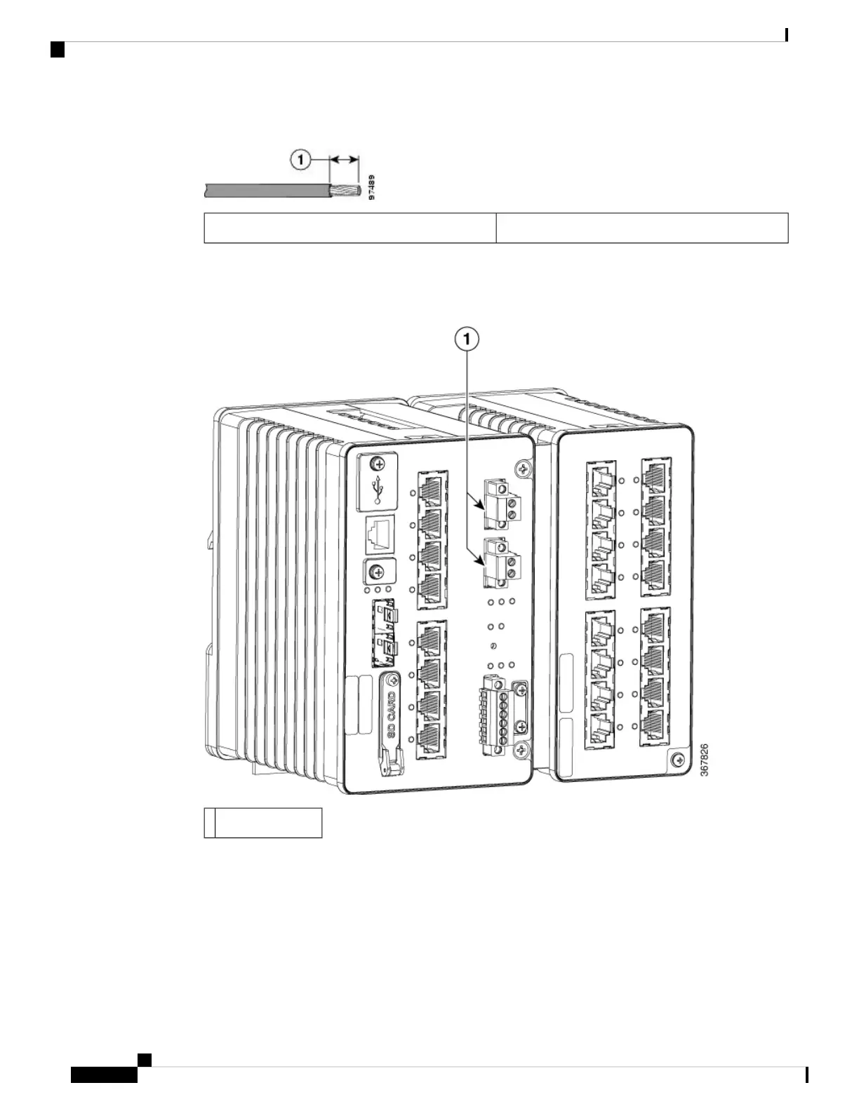
5. Remove the two captive screws that attach the power connector to the switch, and remove the power
connector. Remove both connectors if you are connecting to two power sources.
Figure 5: Removing the Power Connectors from the Switch
Power Connectors1
6. On the power connector, insert the exposed part of the positive wire into the connection labeled “+” and
the exposed part of the return wire into the connection labeled “–”. Make sure that you cannot see any
wire lead. Only wire with insulation should extend from the connector.
Switch Installation
16
Switch Installation
Wiring the DC Power Source

 Loading...