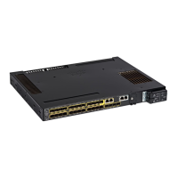
Figure 3: FE Ports
RD
–
3RD
+
1
TD
–
4TD
+
2
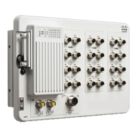
Power Connector
You connect the DC power to the switch through the front panel connector. The power connector labeling is
on the panel. Torque power connection to 10in/lbs.
Figure 4: Power Connector
DC–3NC1
NC4DC+2
Alarm Connector
You connect the alarm signals to the switch through the alarm connector. The switch supports one alarm
output relay.
The alarm output circuit is a relay with a normally open and a normally closed contact. The switch is configured
to detect faults that are used to energize the relay coil and change the state on both of the relay contacts:
normally open contacts close, and normally closed contacts open. The alarm output relay can be used to control
an external alarm device, such as a bell or a light. The alarm output is rated at 24Vdc/1A, 48Vdc/0.5A
maximum.
Cisco Catalyst IE3400 Heavy Duty Series Hardware Installation Guide
4
Product Overview
Power Connector
 Loading...