EasyManuals Logo

Cisco cBR Series User Manual

Cisco cBR Series
12 pages
To Next Page IconTo Next Page
To Previous Page IconTo Previous Page
Page #6 background imageLoading...
Page #6 background image
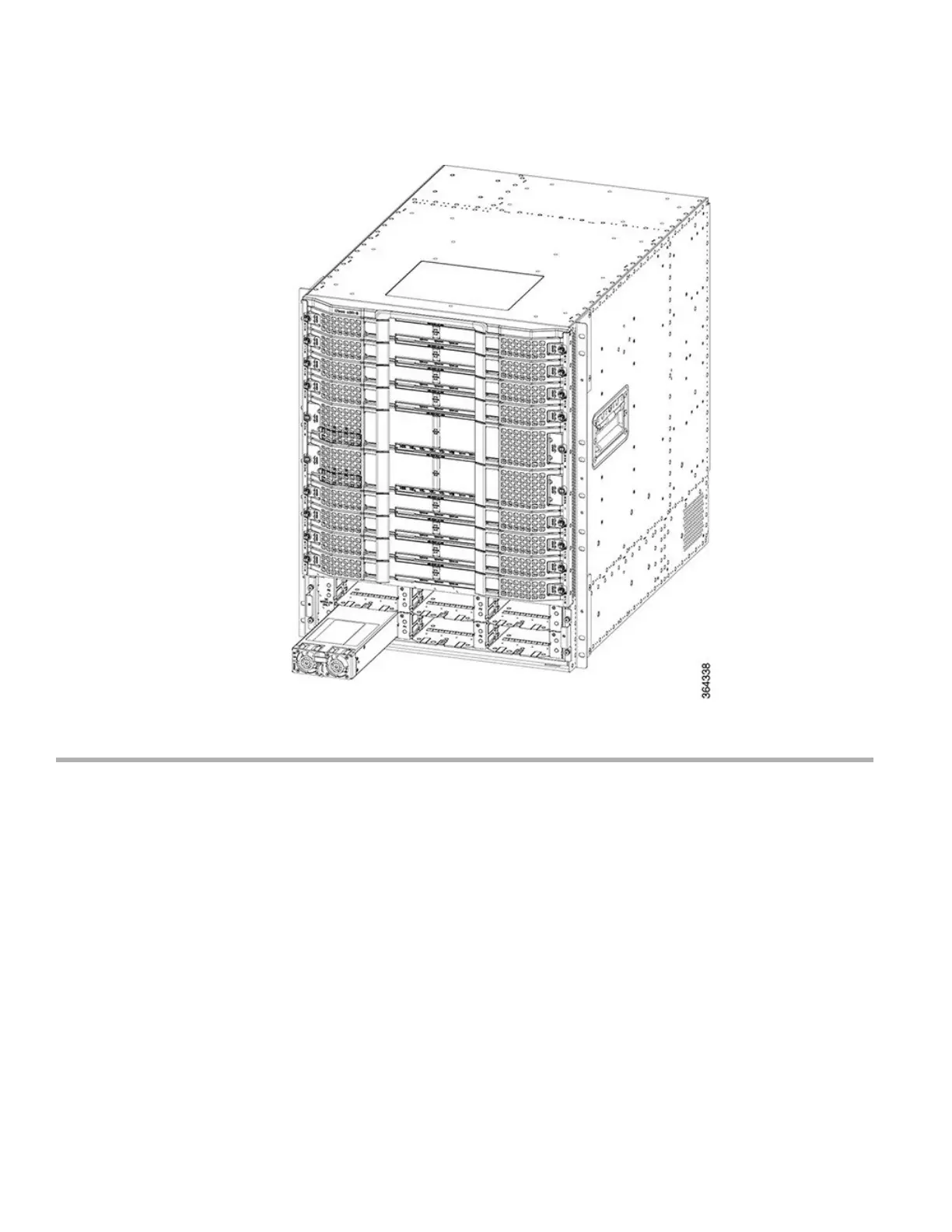
Figure 4: Removing the Power Module
Step 5 Place the removed Power Module in an antistatic bag.
What to do next
Replace the Power Module (if required).
Position the front power entry bezel on the chassis. Insert and tighten the two screws using a 3/16" flat-blade torque screwdriver
with a torque of 5-7 in-lb (0.56-0.79 Nm) to secure the bezel.
Removing the FPEM from the Cisco cBR Chassis
Before you begin
For an AC-powered Cisco cBR chassis, remove the AC power connections.
For an DC-powered Cisco cBR chassis, remove the DC power connections.
Attach an ESD-preventive wrist strap to your wrist and connect the other end to the grounding lug connected to the chassis.
6

Other manuals for Cisco cBR Series

Questions and Answers:

Question and Answer IconNeed help?

Do you have a question about the Cisco cBR Series and is the answer not in the manual?

Cisco cBR Series Specifications

General IconGeneral
CategoryNetwork Router
Modular DesignYes
Operating SystemCisco IOS XE
Model ExamplescBR-8, cBR-4
Product SeriescBR Series
PurposeConverged Broadband Router
DOCSIS SupportDOCSIS 3.1
RedundancyYes
ManagementCisco Prime
Product FamilycBR Series
Downstream Frequency RangeUp to 1.2 GHz
Upstream Frequency RangeUp to 204 MHz
Modulation SchemesQAM
Power SupplyRedundant AC or DC power supplies
Operating Temperature0°C to 40°C
Storage Temperature-40°C to 70°C
Humidity5 to 95% noncondensing

Related product manuals