E-3
Cisco Physical Security Multiservices Platform Series User Guide
OL-21838-03
Appendix E 16 x D1 and 8 x D1 Video Capture Cards
Requirements
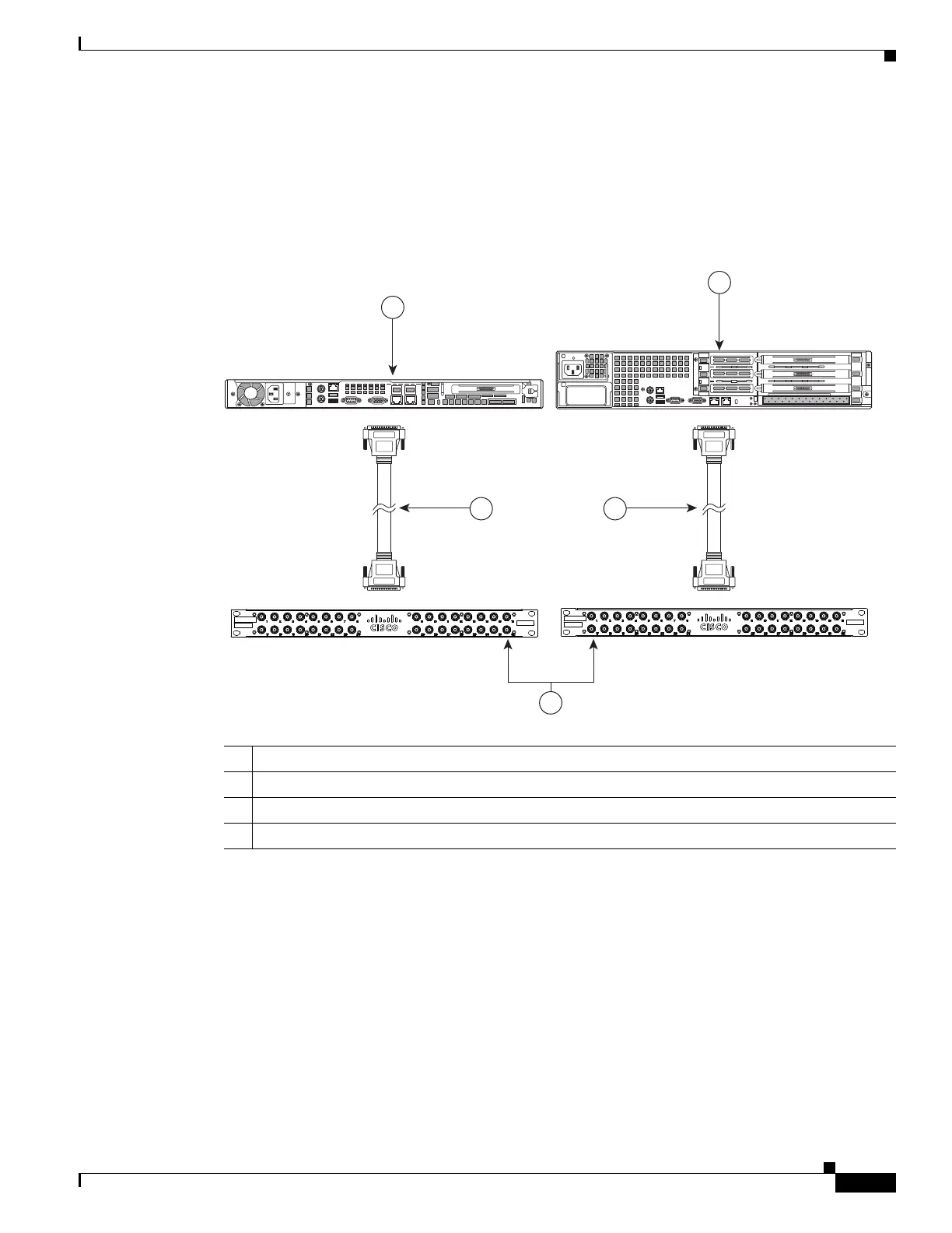
Cisco recommends that a separate BNC breakout panel be used to provide BNC connectors for the
cameras. The breakout panel should be rack-mounted behind the server and connected to the video
capture card with a DB37 multi-channel video cable, as shown in
Figure E-2. See the “Connecting the
Video Capture Card to the BNC Breakout Panel” section on page E-10 for more information.
Figure E-2 Multi Services Platform Series Devices with Optional Video Capture Card, BNC Panel,
and Connecting Cable
See the “Part Numbers” section on page E-12 for more information.
Requirements
The following items are required to support the 16 x D1 and 8 x D1 video capture cards.
• Cisco VSM release 6.3 or higher. See the “Configuration Instructions for Cisco Video Surveillance”
section on page E-14.
• CPS-MSP-1RU-K9 or CPS-MSP-2RU-K9 Multiservices Platform Series with one or more 16 x D1
and 8 x D1 video capture cards.
• BNC breakout panel and multi-channel video cable.
1 1-RU Multiservices Platform Series with installed video capture card
2 2-RU Multiservices Platform Series with installed video capture card
3 Multi-channel video cables
4 BNC breakout panels
 Loading...