E-7
Cisco Physical Security Multiservices Platform Series User Guide
OL-21838-03
Appendix E 16 x D1 and 8 x D1 Video Capture Cards
Understanding Video Channel Numbers
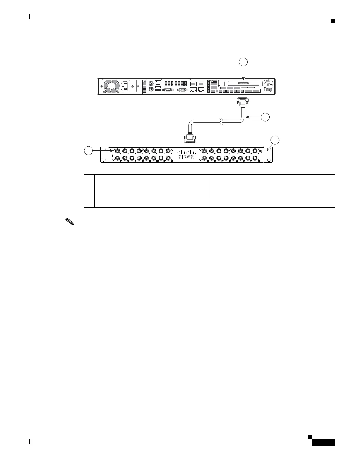
Figure E-4 1-RU Multi Services Platform Series Device Video Capture Card Port Numbers
Note Although you can connect the DB37 cable to the lower connector of the BNC panel, the corresponding
BNC connectors are labeled 17 through 32. The camera channel numbers remain 1 through 16, however,
as determined by the installed location of the card (or channels 1 through 8 for an 8 port card). Cisco
recommends using the top DB37 connector on the BNC panel to avoid confusion.
1 Video capture connection for the 1-RU
Multiservices Platform Series (ports 1
through 16)
3 BNC panel port numbers 1 through 8
2 DB37 multi-channel video cable 4 BNC panel port numbers 9 through 16
 Loading...