Cue Tone/Cue Trigger Interface
The D9800 receiver is equipped with a connector labeled Cue Tone/Relay for alarm relay outputs for remote
alarm signaling. This connector provides Cue Tone, Cue Trigger, and Alarm relay functionality. These outputs
are user-configurable via the Setup Menu on the front panel.
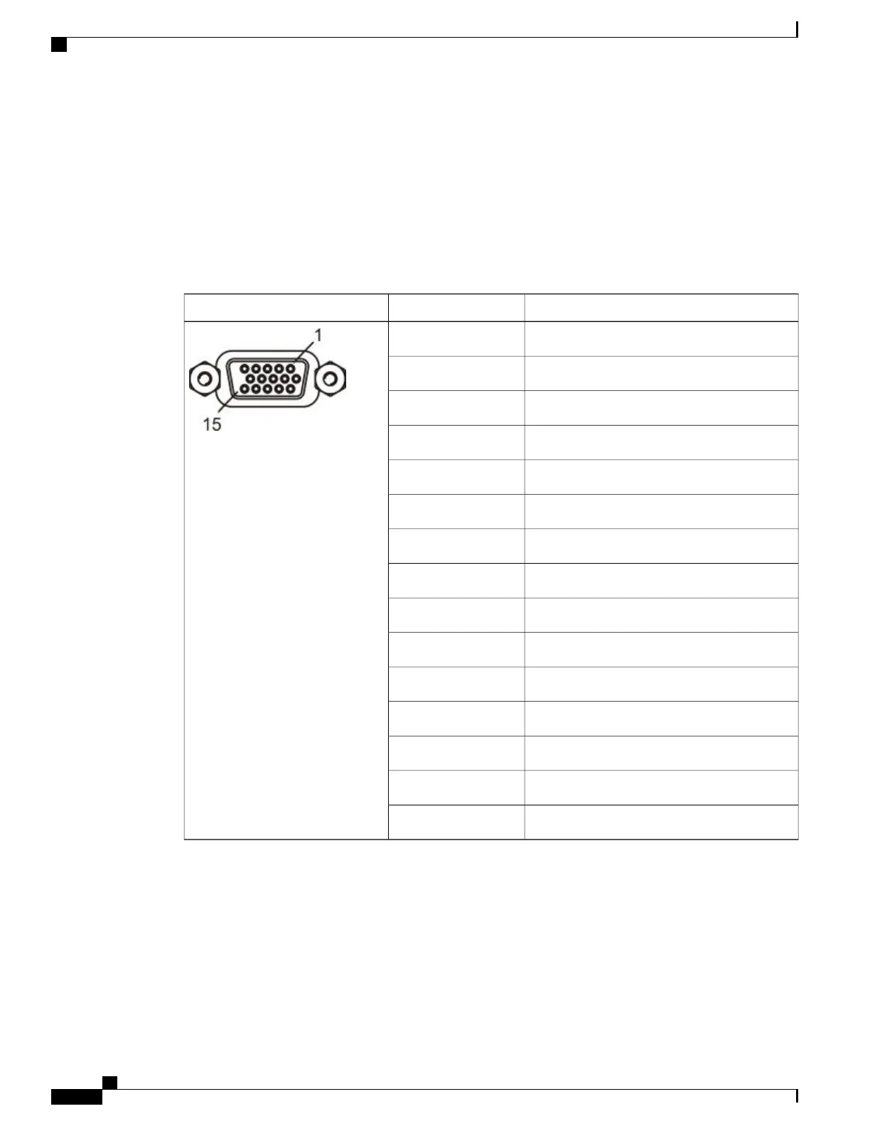
The connector is a 15-pin sub-D female connector, with the voltage and current of SV Vmax 30 mAmax. The
following table shows the connector and the pin allocation table for Cue Tone, Cue Trigger, and Alarm relay
connections.
Pin AllocationPinConnector
Cue Trig 11
Cue Trig 22
Cue Trig 33
Cue Trig 44
Cue Trig 55
Cue Trig 66
Cue Trig 77
Cue Trig 88
Not connected9
Alarm - Ground10
Alarm - Normally open11
Chassis ground12
Cue Tone-13
Cue Tone +14
Alarm - Normally closed15
Connecting the Cue Tone Interface
Connect the Cue Tone pins, 13 and 14 to a device to facilitate ad-insertion using DTMF Analog Cue Tones.
Cisco D9800 Network Transport Receiver Version 3.11 Installation and Configuration Guide
10
Installing the D9800 Network Transport Receiver
Cue Tone/Cue Trigger Interface
 Loading...


