Rear Connector Panels
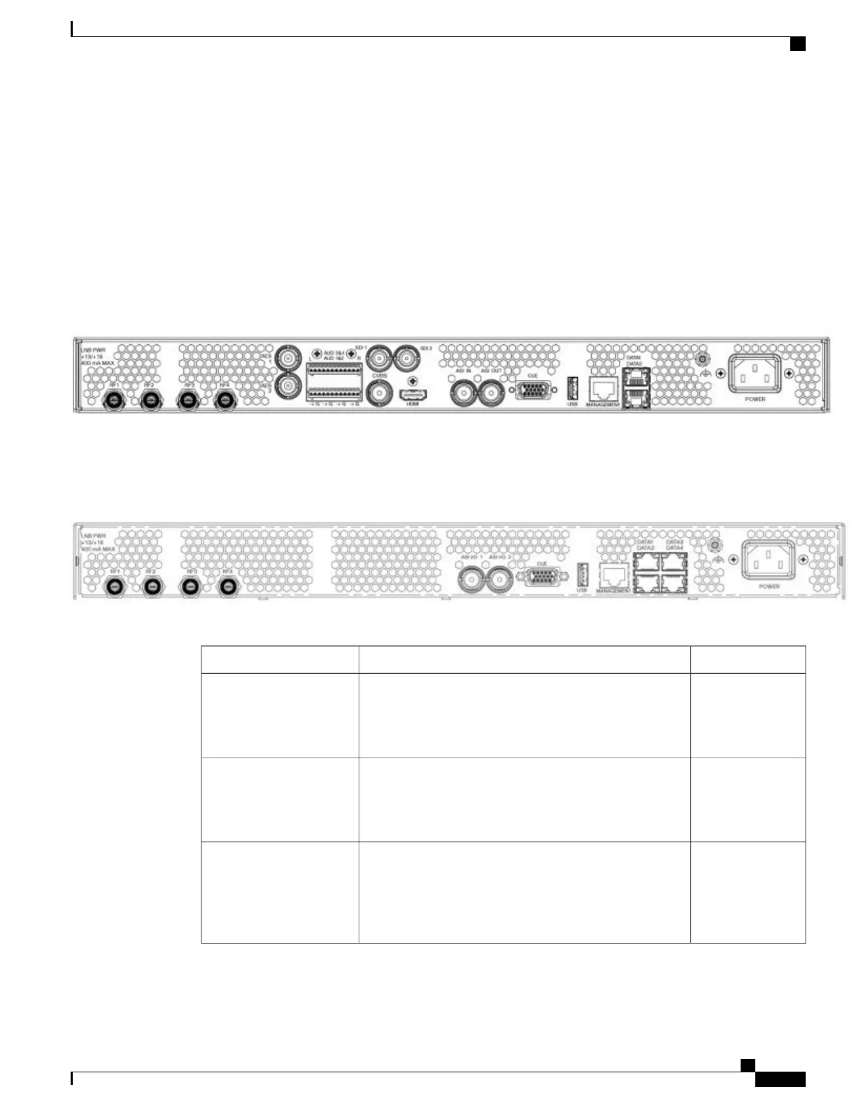
The diagram below shows the rear connector panel of the D9800 base chassis with ASI and MPEGoIP
Input/Output (D9800-SS-MPEGOIP), with SDI (D9800-3G-SDI) and four port satellite input card
(D9800-SAT-GEN1) options installed.
Figure 1: D9800-SS-MPEGOIP Rear Connector Panel, with D9800-3G-SDI and D9800-SAT-GEN1 Options
The diagram below shows the rear connector panel of the D9800 Multi-Stream chassis with ASI and MPEGoIP
(D9800-MS-MPEGOIP), with D9800-SAT-GEN1 option.
Figure 2: D9800-MS-MPEGOIP Rear Connector Panel, with D9800-SAT-GEN1 Option
The table below describes the function and type of the various connectors.
TypeDescriptionConnector
FEach input accepts an LNB signal input. RF1 provides
LNB power for use when no external LNB power source
is available. RF2 to RF4 require an external LNB power
source.
RF1 to RF4
BNCThese are AES-3id outputs. One output for each stereo
channel.
This is only available on single-stream units with
the SDI option installed (D9800-3G-SDI).
Note
AES1 and AES2
Terminal BlocksAudio 1&2 and Audio 3&4 provide two stereo pairs or
four mono channels.
The AUD 3&4 outputs are only available on
single-stream units with the SDI option installed
(D9800-3G-SDI).
Note
AUD 1&2 and AUD 3&4
(Balanced Audio Outputs)
Cisco D9800 Network Transport Receiver Version 3.11 Installation and Configuration Guide
3
Installing the D9800 Network Transport Receiver
Rear Connector Panels