Connecting the ASI Output
Connect the output signal from the D9800 receiver ASI OUT connector.
Use a Belden “Brilliance” cable (or equivalent) with foil/braid construction. The shield must provide 99% or
better shielding effectiveness.
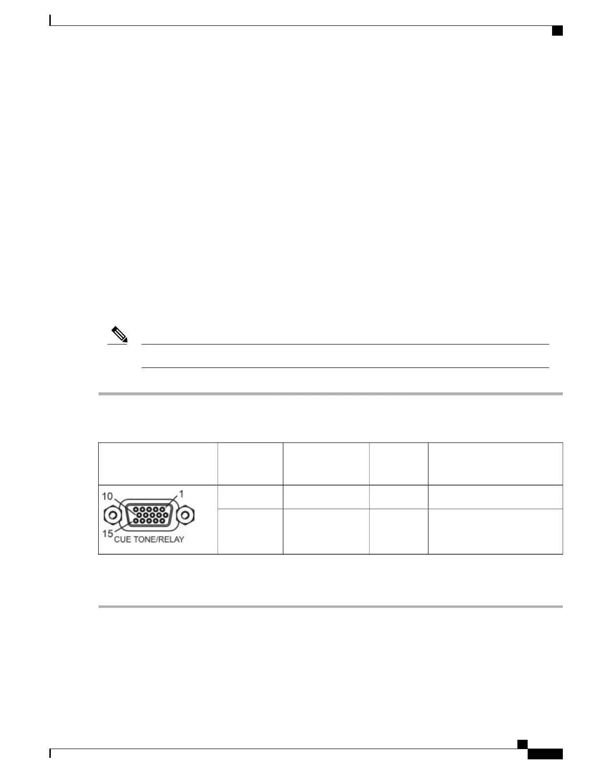
External Alarm System Connector
The Alarm output connector is a 15-pin sub-D female connector. The connector pin states depend on the
selected Relay Mode.
Changing the Relay Mode for Alarm Monitoring
The Alarm relay is a program relay that can be configured to provide programmed responses for alarms,
warnings, and cue trigger states for ad insertion equipment. As a default, the Alarm Relay is configured for
Alarm mode.
The cue tone or cue trigger interface is available on single-stream units only.Note
Step 1
From the Main Menu of the D9800 front panel, choose Setup > Outputs > Cueing > Relay Mode.
Step 2
Choose Alarm.
Step 3
Save your changes. The rear panel connector pin states will change to that shown in the table below for Alarm mode.
Relay ModeOpen in
Normal
Operation
Common PinClosed in
Normal
Operation
Connector
Trigger151011
Alarm (default)111015
A normally closed state implies the state when power is applied to the relay in a normal operating state, without
a trigger or alarm condition present.
Note
Cisco D9800 Network Transport Receiver Version 3.11 Installation and Configuration Guide
9
Installing the D9800 Network Transport Receiver
Connecting the ASI Output