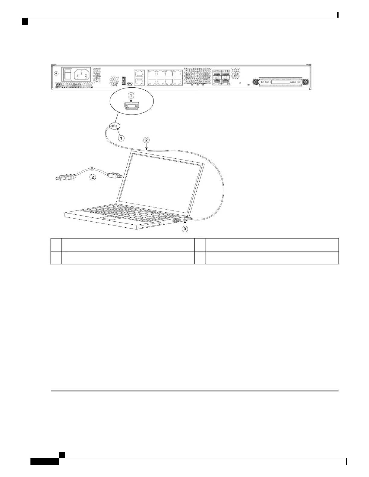
Figure 25: Console Port Connection
USB Mini B to USB Type A console cable2USB Mini B console port1
—USB Type A3
Step 4 Connect the end of the cable with the DB-9 connector (or USB Type A) to the terminal or PC. If your terminal or PC has
a console port that does not accommodate a DB-9 connector, you must provide an appropriate adapter for that port.
The LED for the console port turns green and within a few moments the Found New Hardware Wizard appears.
Step 5 Follow the instructions to complete the driver installation.
Step 6 To communicate with the chassis, start a terminal emulator application. This software should be configured with the
following parameters:
• 9600 baud
• 8 data bits
• no parity
• 1 stop bit
• no flow control
Cisco Firepower 1100 Series Hardware Installation Guide
30
Connect to the Console Port
Connect to the Console Port with Microsoft Windows

 Loading...


