• One FIPS opacity shield (part number 69-100612-01)
• Two cable management brackets (part number 700-117013-01)
• Eight Phillips 8-32 x 0.375-inch screws (part number 48-0629-01) used to attach the FIPS opacity
shield to the cable management brackets
• Ten Tamper Evidence Labels (TEL) (part number 47-25553-01)
The TELs are made of a special thin gauge vinyl with self-adhesive backing.
Once the CO attaches them on the chassis, any attempt to open the chassis
damages the TELs or the chassis cover. Because the TELs have nonrepeated
serial numbers, the CO can inspect them for damage and compare them
against the applied serial numbers to verify whether the chassis has been
tampered with. TELs with curled corners, rips, and slices indicate tampering.
The word “FIPS” or “OPEN” may appear if the label has been peeled back.
Note
Step 1 Copy the serial number and store in a secure place. To find the serial number, see Serial Number Location.
Step 2 Perform the Step 1 as described in Rack-Mount the Chassis, on page 25.
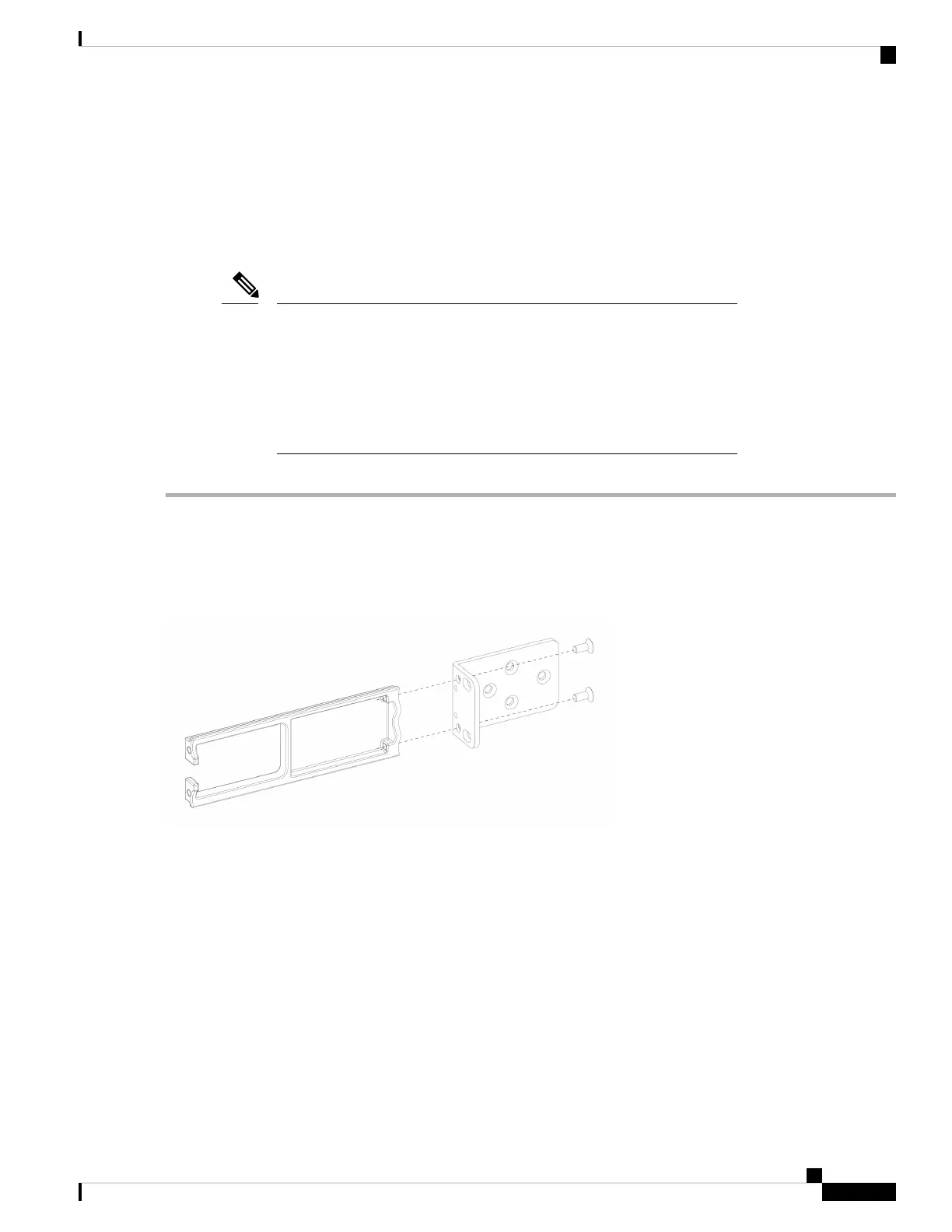
Step 3 Install the cable management brackets.
Figure 27: Install the Cable Management Screws into the Rack-Mount Bracket
Step 4 Connect the cables to the ports. Make sure that the cables have enough slack to route them through the cable mounting
brackets.
If you are installing the FIPS opacity shield after the initial product installation, the cables are connected. If
the attached cables do not have enough slack to route them through the cable mounting brackets (as shown
in the figure below), you will have to turn the power off on the appliance, remove the cables, route the cables
through the cable mounting brackets, reattach the cables, and continue with Step 5 below.
Note
When you toggle the power switch from ON to OFF, it takes several seconds for the system to power down.
Do not remove the power cable until the power LED is off. After removing power from the chassis either by
moving the power switch to OFF or unplugging the power cord, wait at least 10 seconds before turning power
back ON.
Note
Cisco Firepower 1100 Series Hardware Installation Guide
35
Installation, Maintenance, and Upgrade
Install the FIPS Opacity Shield in a Two-Post Rack