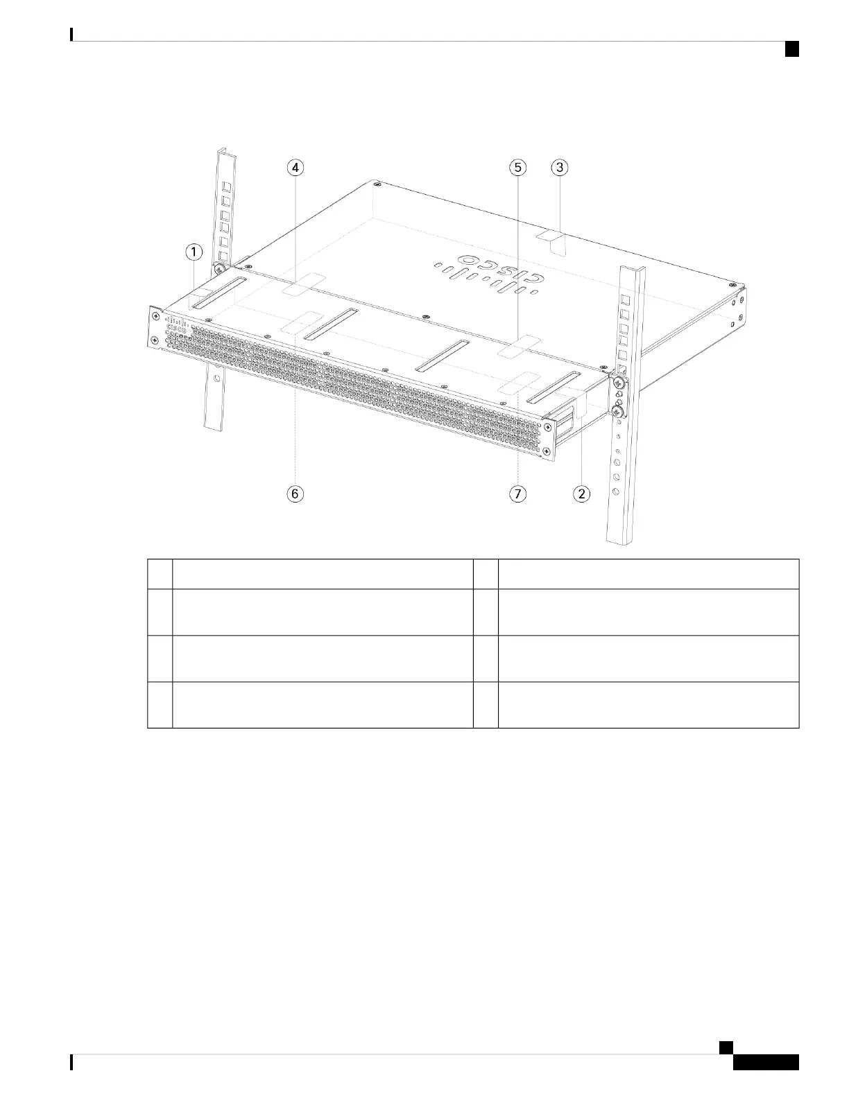
Figure 29: TELs Placement on the Chassis
TEL 2 on the right side and top of chassis2TEL 1 on the left side and top of chassis1
TEL 4 across the FIPS shield and the chassis (towards
the left of the chassis)
4TEL 3 on the top and back of chassis3
TEL 6 on the bottom of the chassis towards the left
side of the chassis
6TEL 5 across the FIPS shield and the chassis (towards
the right of the chassis)
5
—TEL 7 on the bottom of the chassis towards the right
side of the chassis
7
Step 9 Attach the power cable to the chassis and connect it to an electrical outlet.
Step 10 Press the power switch on the rear panel.
Step 11 Check the power LED on the front panel. See Rear Panel LEDs, on page 9 for a description of the power LED. Solid
green indicates that the chassis is powered on.
Step 12 Place the chassis in FIPS mode.
See the following procedures for how to place the chassis in FIPS mode:
• ASA in Platform Mode
• ASA in Appliance mode
Cisco Firepower 1100 Series Hardware Installation Guide
37
Installation, Maintenance, and Upgrade
Install the FIPS Opacity Shield in a Two-Post Rack