Slide rail assemblies work with four-post racks and cabinets with square slots, round 7.1mm holes, #10-32
threaded holes, and #12-24 threaded holes on the rack post front. The slide rail works with front to back
spacing of rack posts from 24 to 36 inches.
Step 1
Attach a rack mount bracket to each side of the chassis using the six 8-32 x .375" countersink Phillip head screws (three
per side) provided in the kit.
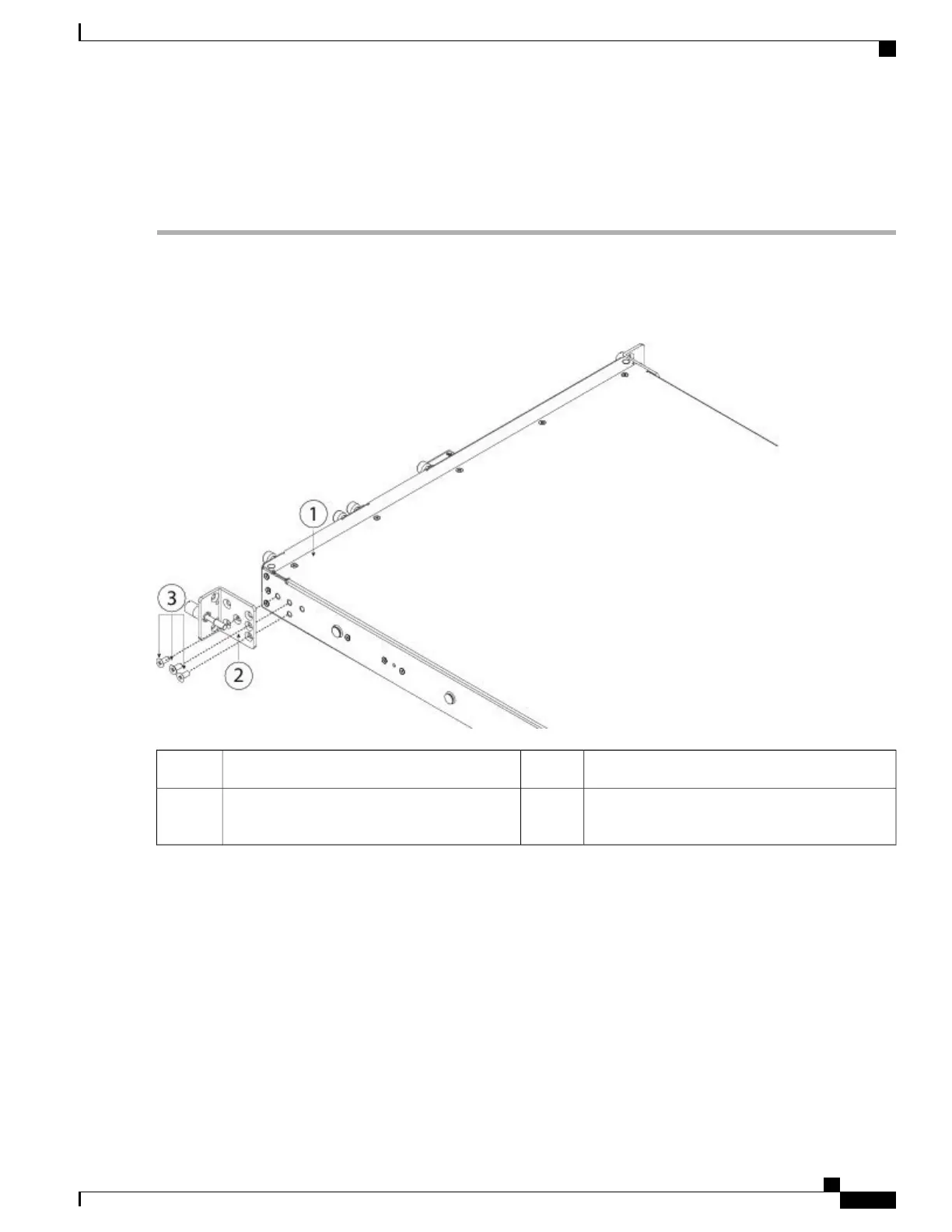
Figure 14: Attaching the Rack Mount Bracket to the Side of the Chassis
Rack mount bracket2Chassis1
8-32 x 0.25" countersink Phillip head screws
(3 per side)
3
Step 2
Attach the inner rails to the sides of the chassis:
a) Remove the inner rails from the slide rail assemblies.
b) Align an inner rail with each side of the chassis:
Cisco Firepower 2100 Series Hardware Installation Guide
35
Mount and Connect
Rack-Mount the Chassis