Statement 1089—Instructed and Skilled Person Definitions
An instructed person is someone who has been instructed and trained by a skilled person and takes
the necessary precautions when working with equipment.
A skilled person or qualified personnel is someone who has training or experience in the equipment
technology and understands potential hazards when working with equipment.
Warning
Statement 1090—Installation by Skilled Person
Only a skilled person should be allowed to install, replace, or service this equipment. See statement
1089 for the definition of a skilled person.
Warning
Statement 1091—Installation by an Instructed Person
Only an instructed person or skilled person should be allowed to install, replace, or service this
equipment. See statement 1089 for the definition of an instructed or skilled person.
Warning
Before you begin
You need the following to connect the DC power supply module:
• Phillips head screwdriver
• 10-mm wrench or socket
• Connectors and wire for the DC circuit or circuits
• Two 2-hole lugs
These lugs are not provided in the accessory kit. We recommend lugs similar to the 90-degree DC Burndy
YAZ6C2TC1490 lug. It accepts ¼-20 threaded studs and has the correct stud spacing.
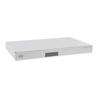
Step 1 Install the DC power supply module in the chassis and make note of the bay number so you can connect the wiring to
the correct terminals on the DC power supply module at the rear of the chassis. See Remove and Replace the Power
Supply Module, on page 17 for the procedure.
Step 2 Verify that the power is off to the DC circuit on the power supply module that you are installing.
Step 3 Make sure that all site power and grounding requirements have been met.
Step 4 Remove the plastic cover from the DC terminals by squeezing the flanges at the top and bottom of the cover.
Step 5 Using the screws, connect the green ground wires to the chassis ground terminal.
Only one ground connection is required even though there may be up to two DC connections.
Step 6 Using the screws, connect the two 2-hole lugs to the power supply module terminal block.
Installation, Maintenance, and Upgrade
24
Installation, Maintenance, and Upgrade
Connect the DC Power Supply Module

 Loading...