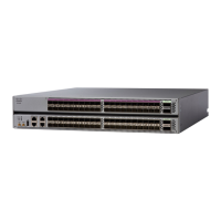
Airflow Direction
The airflow through the fan trays and power supplies on the Cisco NCS 5000 series router is either from the
port side exhaust or the port side intake, depending on how the modules were ordered. To ensure proper
airflow, you must make sure that when you install the switch its air intake is positioned in a cold aisle and the
air exhaust is positioned in a hot aisle for your data center.
Transceivers, Connectors, and Cables
Transceiver and Cable Specifications
To determine which transceivers and cables are supported by this router, see Cisco Transceiver Modules
Compatibility Information.
To see the transceiver specifications and installation information, see Cisco Transceiver Modules Install and
Upgrade Guides.
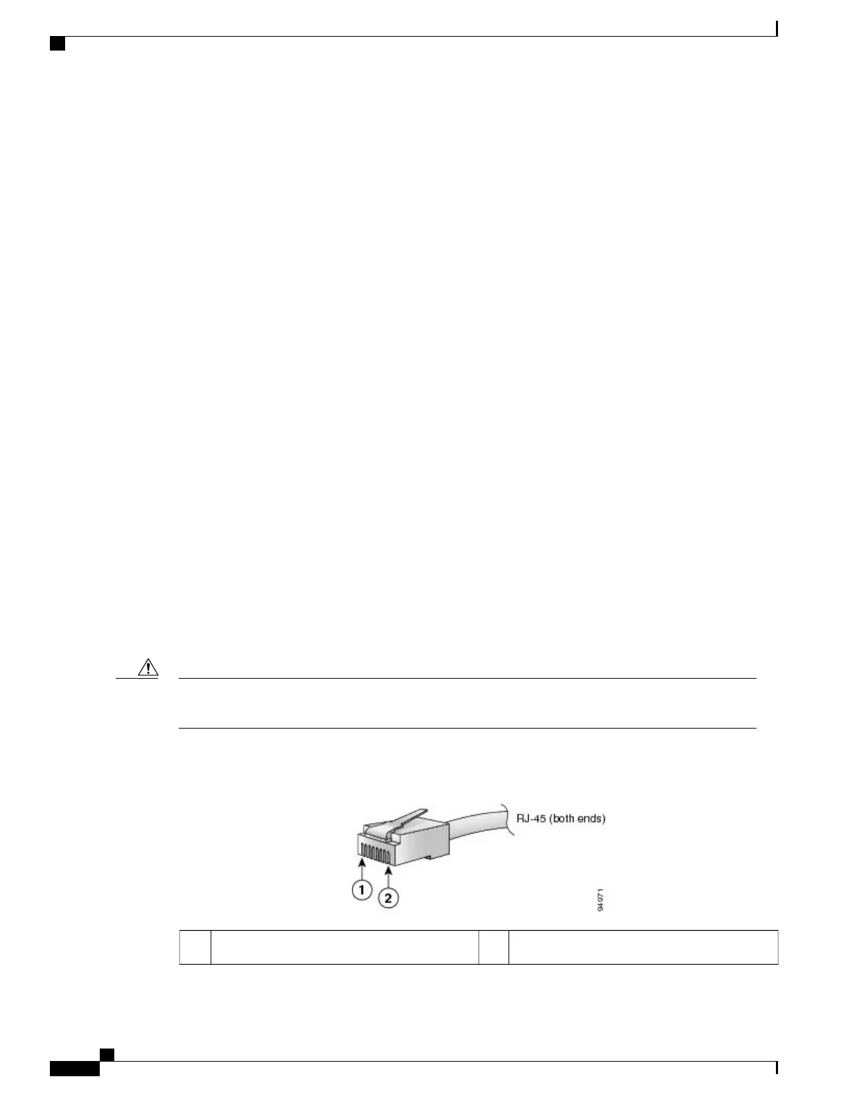
RJ-45 Connectors
The RJ-45 connector connects Category 3, Category 5, Category 5e, Category 6, or Category 6A foil twisted-pair
or unshielded twisted-pair cable from the external network to the following module interface connectors:
•
Router chassis
◦
CONSOLE port
◦
MGMT ETH port
To comply with GR-1089 intrabuilding, lightning immunity requirements, you must use a foil twisted-pair
(FTP) cable that is properly grounded at both ends.
Caution
The following figure shows the RJ-45 connector.
Figure 37: RJ-45 Connector
Pin 22Pin 11
Hardware Installation Guide for Cisco NCS 5500 Series Fixed-Port Routers
68
System Specifications
Airflow Direction