7-2
Cisco PIX Firewall Hardware Installation Guide
78-15170-01
Chapter 7 PIX 535
PIX 535 Product Overview
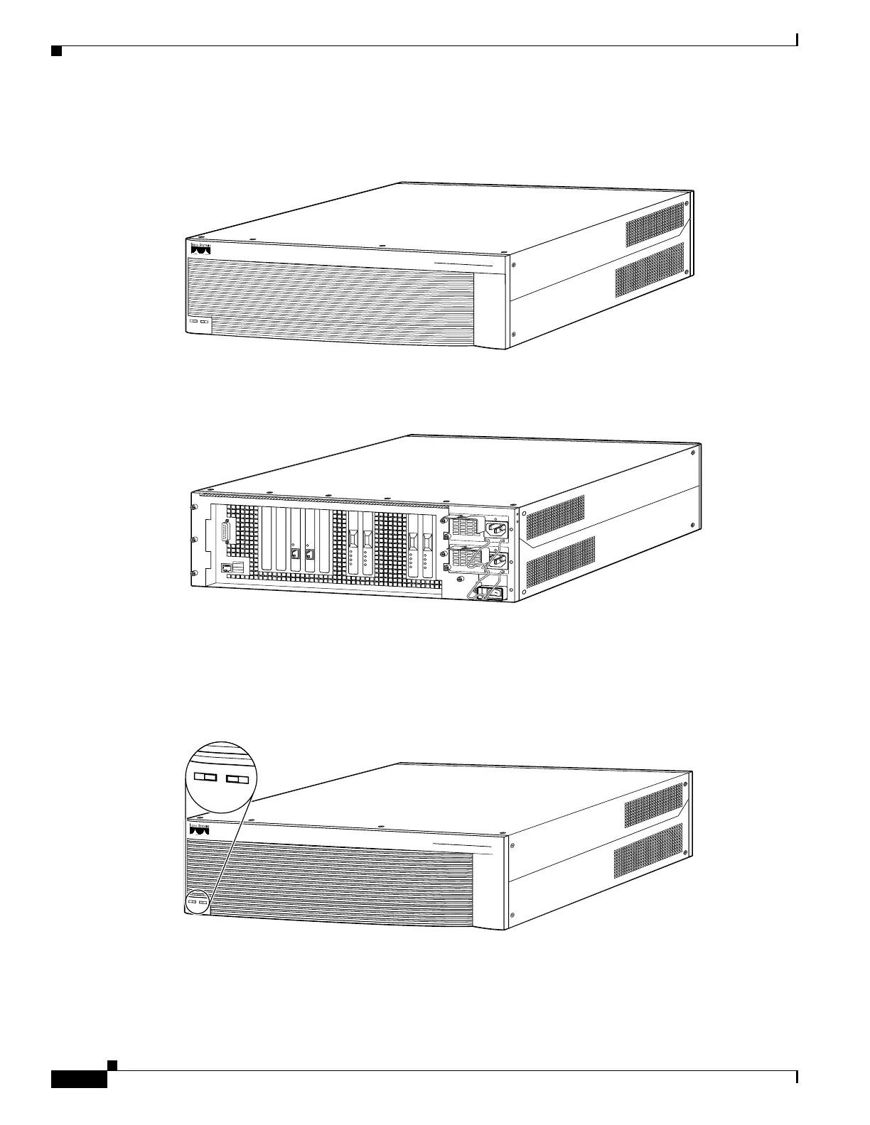
Figure 7-1 shows the front view of the PIX 535.
Figure 7-1 PIX 535 Front Panel
Figure 7-2 shows the rear view of the PIX 535.
Figure 7-2 PIX 535 Rear Panel
The PIX 535 has a fixed RJ-45 Console connector and a DB-15 Failover cable connector the USB port
is not used at the present time.
Figure 7-3 shows the PIX 535 front panel LEDs.
Figure 7-3 PIX 535 Front Panel LEDs
.
61915
CISCO SECURITY PIX 535
S
E
R
IE
S
F
IR
E
W
A
L
L
P
O
W
E
R
A
C
T
I
V
E
61916
S
T
A
T
U
S
S
T
A
T
U
S
61918
CISCO SECURITY PIX 535
S
E
R
IE
S
F
IR
E
W
A
L
L
P
O
W
E
R
A
C
T
I
V
E
POWER ACTIVE

 Loading...