7-3
Cisco PIX Firewall Hardware Installation Guide
78-15170-01
Chapter 7 PIX 535
PIX 535 Product Overview
Table 7-1 lists the state of the PIX 535 front panel LEDs.
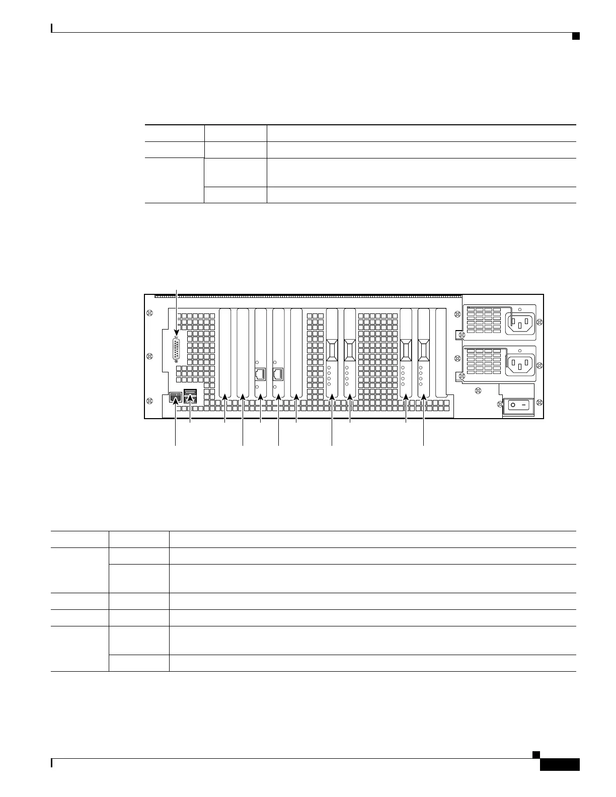
Figure 7-4 shows the PIX 535 rear panel LEDs.
Figure 7-4 PIX 535 Rear Panel LEDs
Table 7-2 lists the state of the PIX 535 LEDs.
Table 7-1 PIX 535 Front Panel LEDs
LEDs Status Description
POWER On Unit has power.
ACT On On when the unit is the active failover unit. If failover is present the light
is on when the unit is the active unit.
Off Off when the unit is in standby mode.
61919
Slot 1
Slot 0
Slot 6Slot 8
Slot 7Console
RJ-45
DB-15
failover
USB
port
Slot 4
Slot 5
Slot 2
Slot 3
Table 7-2 PIX 535 Rear Panel LEDs
LEDs Status Description
100 Mbps On 100 megabits per second 100BaseTX communication.
Off If the light is off during network activity, that port is using 10 megabits per second data
exchange.
ACT On Shows network activity.
LINK Shows that data is passing through that interface.
FDX On Shows that the connection uses full-duplex data exchange where data can be transmitted and
received simultaneously.
Off If this light is off, half duplex is in effect.

 Loading...